Snare

a snare device and snare tube technology, applied in the field of snare, can solve the problems of emboli not being fully vaporized and thus entering the bloodstream, affecting the patient's health, and causing severe injuries to patients, so as to improve the radial and angular resistance to collapse, and restore the patency of blood vessels.

Inactive Publication Date: 2005-10-06
PALMER OLIN +4
View PDF18 Cites 130 Cited by
  • Summary
  • Abstract
  • Description
  • Claims
  • Application Information

AI Technical Summary

Benefits of technology

[0016] Briefly and in general terms, the present invention is directed towards snares for removing undesired material or objects and restoring patency of blood vessels. The snare is a linked or monolithic framework of thin struts that is radially expansible. The snare of the present invention embodies a structure that provides a consistent radial opening as well as improved radial and angular resistance to collapse. That is, as the device is pulled such as through a vessel, the entrance thereto will not fall back or tip over. Moreover, the snare device maintains clearance in its interior space along its length allowing the material or objects to enter and be captured.
[0018] Overall, the intent of the invention is to provide a structure that has the capacity to engage and retain naturally occurring or foreign bodies while having a minimal profile that can traverse easily and repeatably through a standard microcatheter across tortuous anatomy. The device embodies superior flexibility to be deployed and retrieved consistently across difficult anatomy while being able to retain captured material. The inner diameter of the device is heat-set to a pre-determined size. It is envisioned that there be a family of devices that have varying strut lengths, thicknesses, flexibility, and diameters as deemed appropriate for the specific type of vascular or non-vascular setting for which the device is to be used.
[0021] Moreover, the present invention embodies a tip for an endovascular device including an atraumatic soft coil for preventing damage to tissue and facilitates advanceability. The tip further includes multiple layers of coiled material to enhance these objectives as well as to provide stiffness variations.

Problems solved by technology

However, there is one common problem which can become associated with all of these types of procedures, namely, the potential release of embolic debris into the bloodstream that can occlude distal vasculature and cause significant health problems to the patient.
Additionally, while complete vaporization of plaque is the intended goal during a laser angioplasty procedure, quite often particles are not fully vaporized and thus enter the bloodstream.
When any of the above-described procedures are performed in the carotid arteries, cerebral vasculature, or neurovasculature, the release of emboli into the circulatory system can be extremely dangerous and sometimes fatal to the patient.
Naturally occurring debris can also be highly dangerous to a patient.
Debris that is carried by the bloodstream to distal vessels of the brain can cause these cerebral vessels to occlude, resulting in a stroke, and in some cases, death.
Therefore, although cerebral percutaneous transluminal angioplasty has been performed in the past, the number of procedures performed has been limited due to the justifiable fear of causing an embolic stroke should embolic debris enter the bloodstream and block vital downstream blood passages.
However, it is often difficult to control the size of the fragments which are formed, and the potential risk of vessel occlusion still exists, making such a procedure in the carotid arteries a high-risk proposition.
In addition, the retrieval of fragmented clot may be incomplete, also resulting in emboli and distal occlusions, and further, access through tortuous lumens may prove difficult.
Local disruption may open up a proximal occlusion but also may cause significant distal emboli.
However, as mentioned above, there have been complications with such systems since the vacuum catheter may not always remove all of the embolic material from the bloodstream, and a powerful suction could otherwise cause problems to the patient's vasculature.
Other techniques which have had some limited success include the placement of a filter or trap downstream from the treatment site to capture embolic debris before it reaches the smaller blood vessels downstream.
However, there have been problems associated with conventional filtering systems as well.
In particular, certain previously developed filtering devices do not optimize the area for embolic collection.
That is, conventional filtering devices may not present a collection device that spans the entity of the vessel or it may include supporting structure that itself impedes emboli collection.
Certain other devices do not embody sufficient angular resistance to collapse.
However, in addition suffering from the same disadvantages as certain conventional filter devices, such devices have been found to have structures which are either highly complex or lacking in sufficient or effective expansion and retraction capabilities.
Disadvantages associated with the devices having highly complex structure include difficulty in manufacturability as well as use in conjunction with microcatheters.
Other less complex devices can pull through clots due to in part to the lack of experience in using the same or otherwise lack an expanded profile that is adequate in capturing clots or foreign bodies.
Thrombo-embolic materials can be friable, amorphous, and / or lubricious in nature contributing to this difficulty.
These devices may have limited effectiveness, due in part to the lack of encapsulation.
Objects are difficult to grasp within these devices, and friable objects, e.g. blood-based blockages, tend to fragment when grasped or pulled, introducing multiple emboli.
These typically have the disadvantages of lengthy treatment / infusion times to remove the obstruction (>3 hrs.
Also, these drugs are not typically effective in removing obstructions that are not blood-based.

Method used


Image

  • Snare
  • Snare
  • Snare

Examples


first embodiment

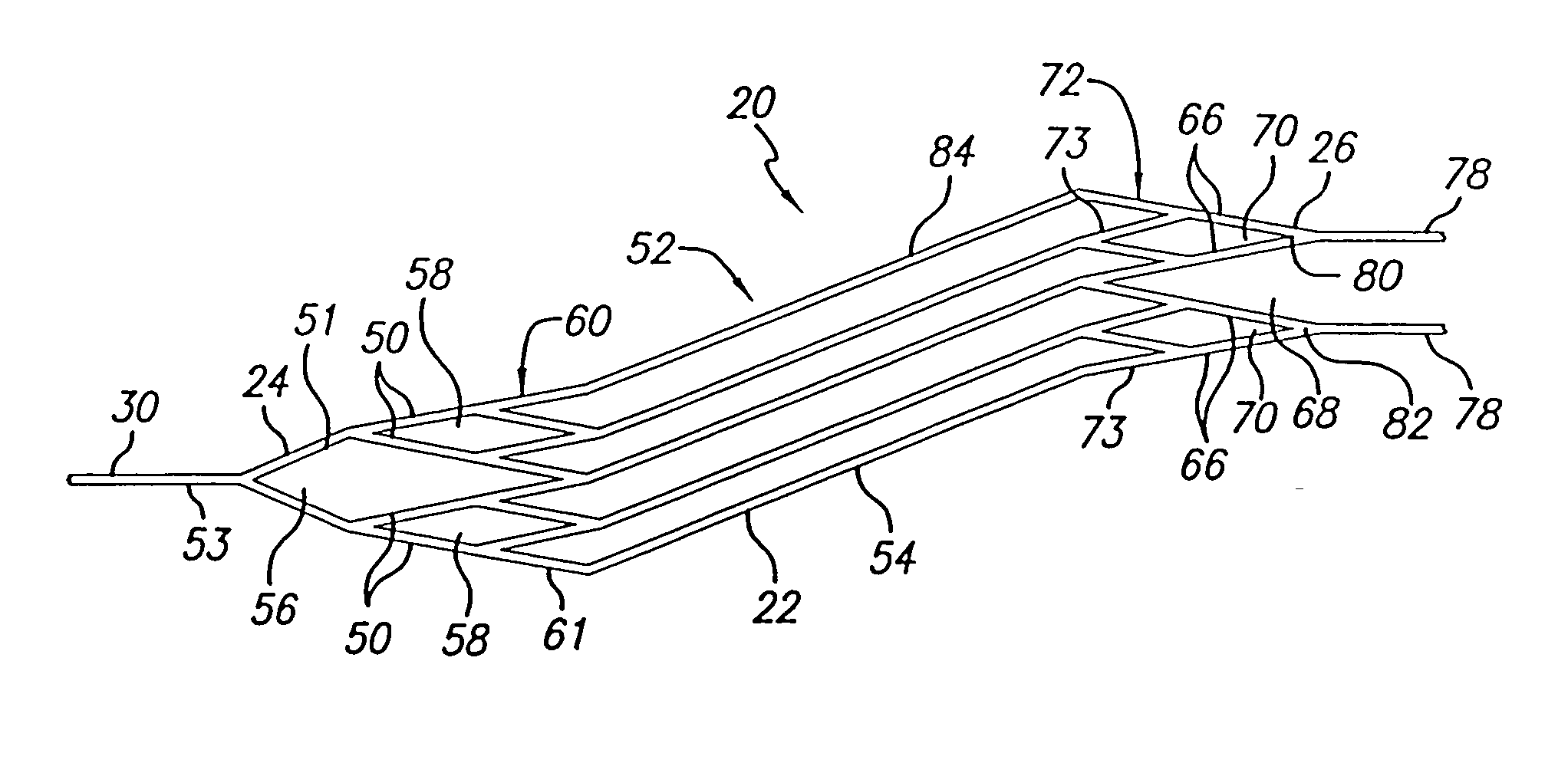
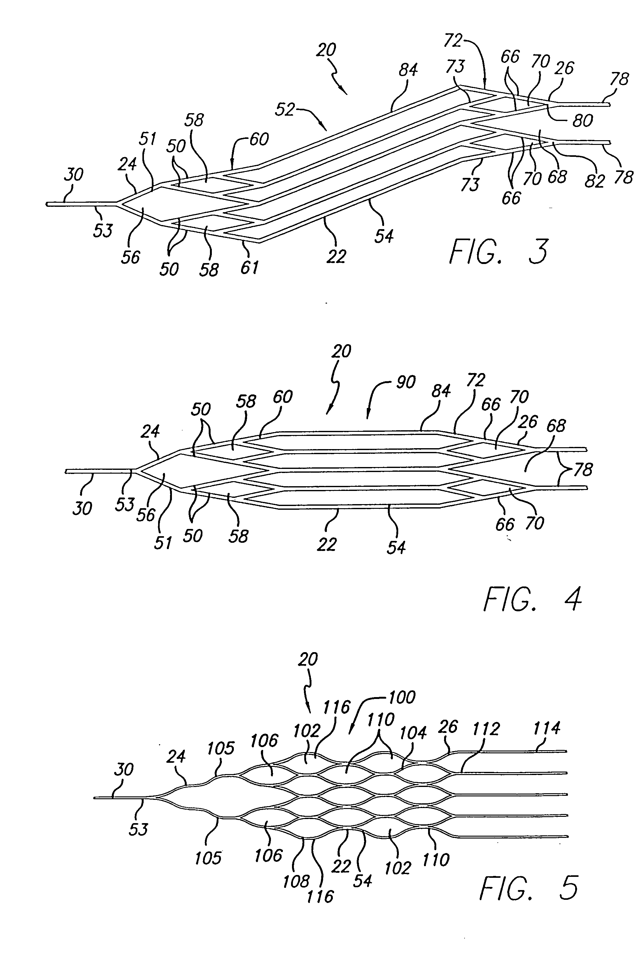
[0061] In an alternative embodiment of a snare pattern 90 (FIG. 4), the proximal end and distal end portions 24, 26 also include members 50, 51, 66 which define proximal and distal parallelogram-shaped apertures 58, 70 as well as a diamond-shaped aperture 56 and an open ended triangle 68. This second snare pattern 90 also similarly includes proximal and distal rings 60, 72 as well as distally directed extensions 78, each of which are joined to one of the distal parallelogram-shaped apertures 70. Moreover, the midsection 54 of the pattern 90 includes a plurality of parallel, longitudinally extending members 84 which are joined to the structure defining the proximal and distal end portions 24, 26. This embodiment differs from the first embodiment, however, in that the longitudinally extending members are not helically configured when the pattern 90 is in its as cut form. Rather, while defining a sidewall of a generally tubular midsection 54, each of the longitudinally extending member...

fourth embodiment

[0072] As with the fourth embodiment, a single member 152 extends from each of the four crowns 147, 148 in both proximal and distal directions. Further, the four members 152 connected to the proximal crowns 147 converge into two members 154, each of which again converge to form a proximal tab 156. At the distal end of the device 20, adjacent pairs of the single members 152 converge to a single extension 158. Again, the terminal ends 158 may be joined using soldering, laser welding, adhesive, shrink wrap, or by employing a coil configured about adjacent structure.

[0073] Referring now to FIG. 12, there is shown one preferred embodiment of the elongated member 30 of the present invention. The member 30 embodies a gradual or step-tapered core comprising a proximal section of 304V stainless steel and a distal section of nitinol or an equivalent material for the intended purpose. A proximal portion 160 of the member 30 has a generally constant cross-sectional profile and a first diameter ...


PUM


Abstract

An intravascular snare device for use in capturing debris found in blood vessels. The snare device is fabricated from a tube and includes longitudinally and circumferentially extending members. The snare device specifically embodies structure that provides enhanced radial opening and angular resistance to collapse.

Description

BACKGROUND OF THE INVENTION [0001] The present invention relates generally to intravascular snare devices and systems and more particularly, devices which can be used to capture embolic material or thrombi found in blood vessels. [0002] The intravascular snare device and system of the present invention is particularly useful when performing balloon angioplasty, stenting procedures, laser angioplasty or atherectomy in critical vessels where the release of embolic debris into the bloodstream can occlude the flow of oxygenated blood to the brain or other vital organs, which can cause devastating consequences to the patient. The snare device is also suited for the removal of clots adhering to vessel walls. While the snare device and system of the present invention is particularly useful in the cerebral vasculature and neurovasculature, the invention can be used in conjunction with any vascular interventional procedure in which there is an embolic risk. [0003] A variety of non-surgical i...

Claims


Application Information

Patent Timeline
Patent Type & Authority Applications(United States)
IPC IPC(8): A61B17/22A61F2/06A61M29/00
CPCA61B17/221A61B2017/00526A61B2017/2212
Inventor PALMER, OLINSHEN, CHRISTOPHER T.LADUCA, ROBERTVOSS, LARRYPHONTHALASA, SAYPIN
Owner PALMER OLIN
Why Eureka
Try Eureka