
Field replacable sensor module and methods of use thereof

a sensor module and field technology, applied in the field of field replacement of sensor modules, can solve the problems of connection reliability challenges, actual portion of the device that utilizes the sensor needs replacement,

Inactive Publication Date: 2005-10-06
WESTLOCK CONTROLS
View PDF4 Cites 26 Cited by
  • Summary
  • Abstract
  • Description
  • Claims
  • Application Information

AI Technical Summary

Benefits of technology

[0008] A field replaceable sensor module of this invention comprises a housing, the housing being configured such that the housing is capable of being ready connected and disconnected to a multipurpose device and including one or more pressure input ports, and one or more electrical interface connectors, one or more pressure sensors operatively connected to the one or more input ports and attached to a surface of the housing, an electrical subsystem capable of receiving one or more signals from the one or more pressure sensors and capable of providing one or more digitized output signals, and a computer readable memory having data stored therein, the data comprising sensor calibration data. The electrical subsystem and the computer readable memory are electrically connected to the one or more electrical interface connectors such that the one or more digitized output signals are available from the one or more electrical interface connectors and the computer readable memory is accessible from the one or more interface connectors. The electrical subsystem and the computer readable memory are disposed on a surface of the housing. The module can also include a temperature sensor. In the embodiment that includes the temperature sensor, the computer readable memory has data stored therein that describes the temperature effects on calibration.

Problems solved by technology

Thus, servicing a sensor or the actual portion of the device that utilizes the sensor requires replacement or re-calibration in the field.
Such a connection presents reliability challenges.

Method used


Image

  • Field replacable sensor module and methods of use thereof
  • Field replacable sensor module and methods of use thereof
  • Field replacable sensor module and methods of use thereof

Examples


Embodiment Construction

[0020] Method and systems for providing a field replaceable sensor module are described hereinbelow.

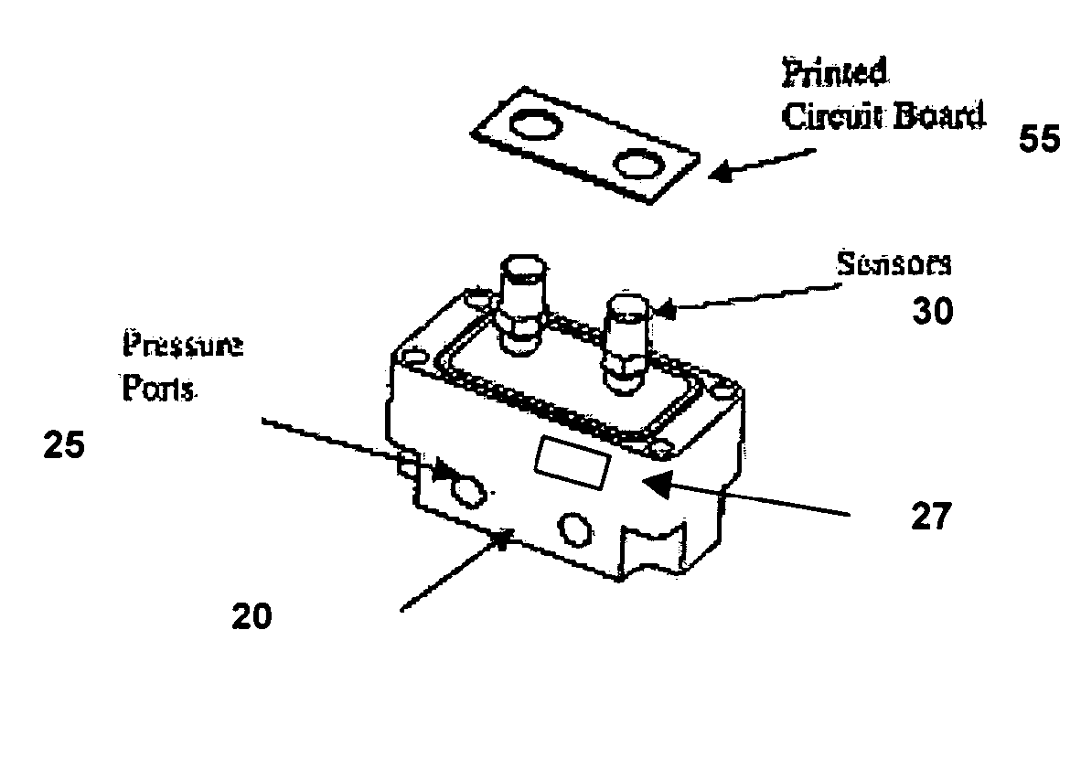
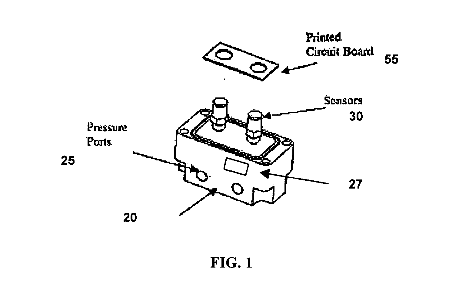
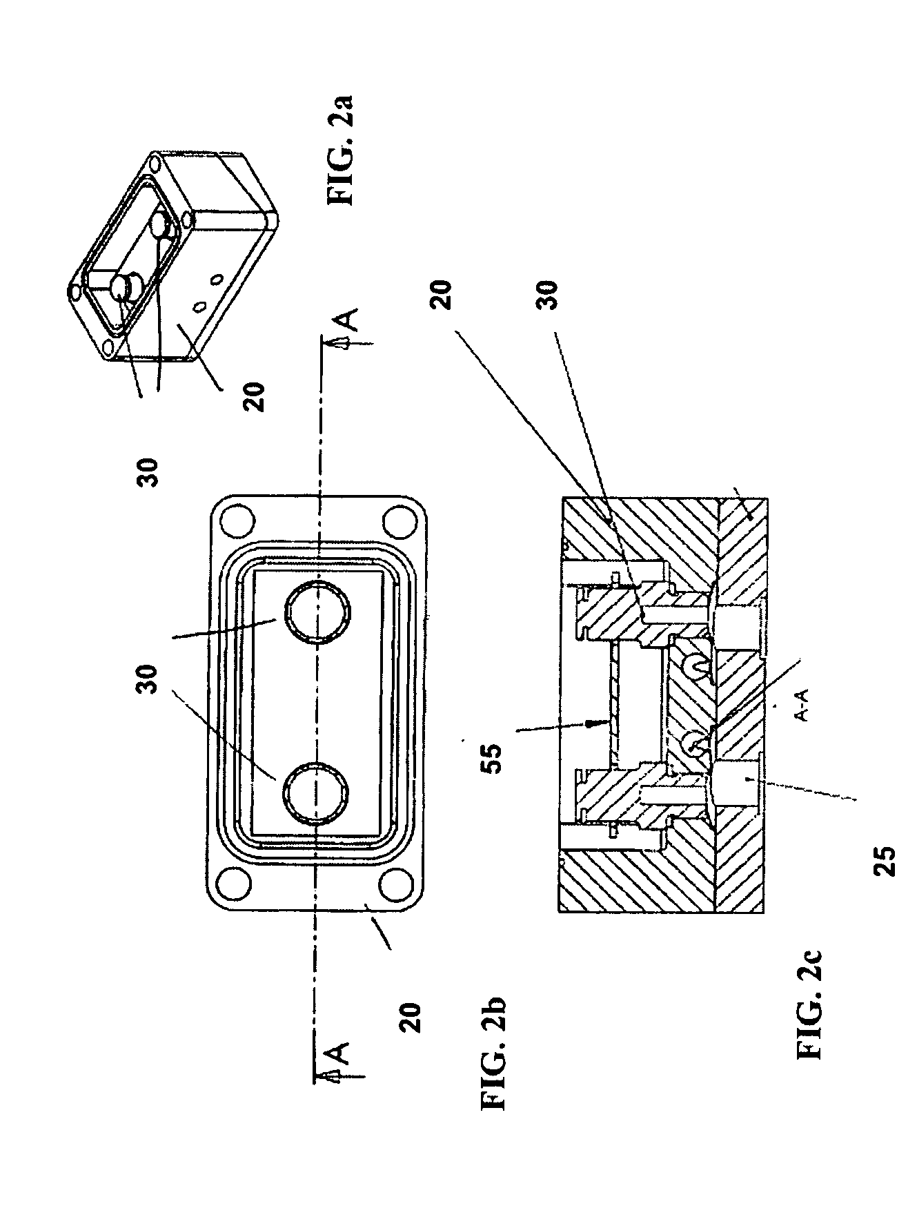
[0021] A schematic pictorial representation of an embodiment of the field replaceable sensor module 10 of this invention is shown in FIG. 1. A block diagram representation of an embodiment of the field replaceable sensor module of this invention is shown in FIG. 3. Referring to FIGS. 1 and 3, the field replaceable sensor module 10 of this invention includes a housing 20, one or more pressure sensors 30, an electrical subsystem 40 (FIG. 3), and a computer readable memory 50 (FIG. 3). In one embodiment, the field replaceable sensor module 10 also includes a temperature sensor 60 (FIG. 3). The temperature sensor 60 could be located in the interior of the housing 20 or in any location in the housing from which a temperature characteristic of the pressure sensors 30 can be determined. The housing 20 is capable of being readily connected and disconnected to a multipurpose device (90, FIG. ...


PUM

PropertyMeasurementUnit
pressureaaaaaaaaaa
electricalaaaaaaaaaa
temperatureaaaaaaaaaa

Abstract

A field replaceable sensor module. The field replaceable sensor module of this invention comprises a housing, the housing being configured such that the housing is capable of being ready connected and disconnected to a multipurpose device and including one or more input ports, and one or more electrical interface connectors, one or more sensors operatively connected to the one or more input ports and attached to a surface of the housing, an electrical subsystem capable of receiving one or more signals from the one or more sensors and capable of providing one or more digitized output signals, and a computer readable memory having data stored therein, the data comprising sensor calibration data.

Description

CROSS REFERENCE TO RELATED APPLICATIONS [0001] This application and claims priority of U.S. Provisional Patent application Ser. No. 60 / 559,945, entitled FIELD REPLACEABLE SENSOR MODULE AND METHODS OF USE THEREOF, filed on Apr. 6, 2004, which is incorporated by reference herein.BACKGROUND OF THE INVENTION [0002] This invention relates generally to sensors and sensor modules. [0003] In a variety of applications, pressure sensor or modules are utilized as part of or in conjunction with multipurpose devices. In those applications, replacement of a pressure sensor module typically requires re-calibration of the pressure sensor in conjunction with the multipurpose device. That is, the pressure sensors have to be calibrated along with the actual portion of the device that utilizes the pressure sensor output, rendering the pressure sensors and the device a matched set. Thus, servicing a sensor or the actual portion of the device that utilizes the sensor requires replacement or re-calibratio...

Claims


Application Information

Patent Timeline
Patent Type & Authority Applications(United States)
IPC IPC(8): G01D3/02G01D11/24G01L27/00G06F19/00
CPCG01D3/022G01D11/245G01L27/002G16Z99/00G01L19/08G01L19/14G08C17/00
Inventor BAIRD, ALISTAIR R.W.SPOCK, THOMAS F.
Owner WESTLOCK CONTROLS
Learn More