Torque wrench with fastener indicator and system and method employing same

a technology of torque wrenches and indicators, which is applied in the field of hand tools, can solve the problems of thread slipping, inefficiency in recording and controlling torque values, and inaccuracy of torque values in many ways

a technology of torque wrenches and indicators, which is applied in the field of hand tools, can solve the problems of thread slipping, inefficiency in recording and controlling torque values, and inaccuracy of torque values in many ways

US20050223856A1Inactive Publication Date: 2005-10-13RYESON CORP

Image

  • Torque wrench with fastener indicator and system and method employing same
  • Torque wrench with fastener indicator and system and method employing same
  • Torque wrench with fastener indicator and system and method employing same

Examples


Embodiment Construction

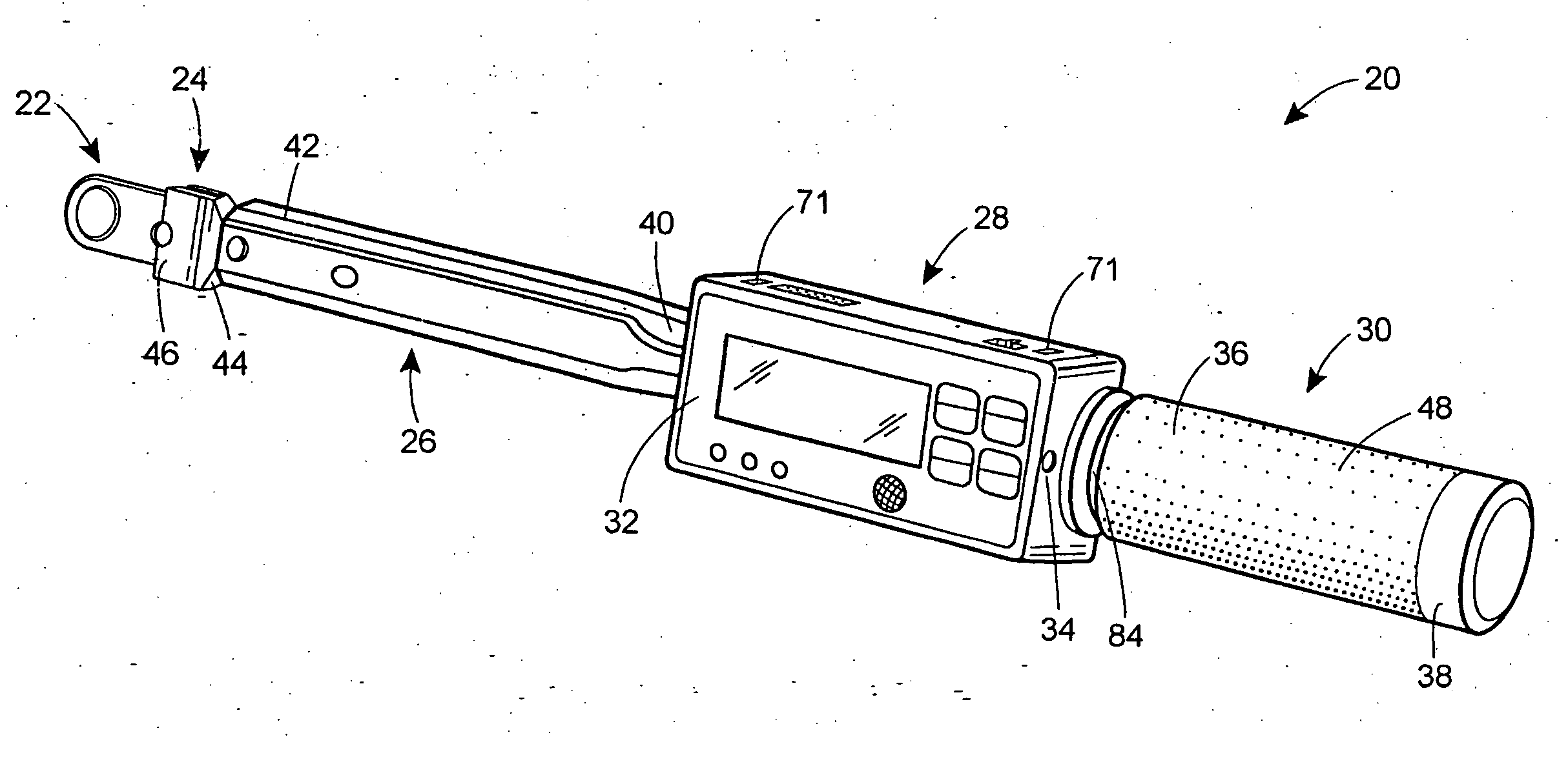
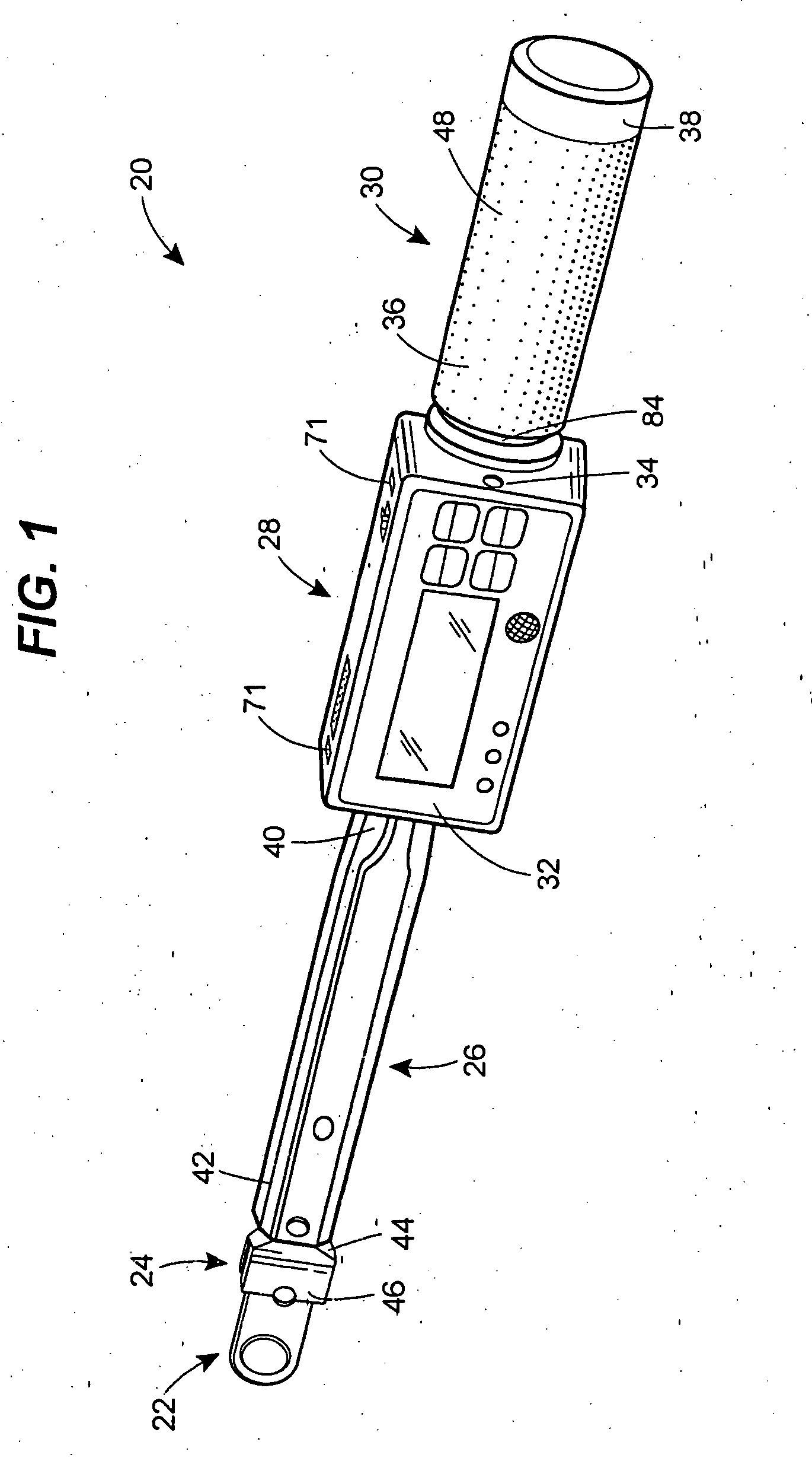
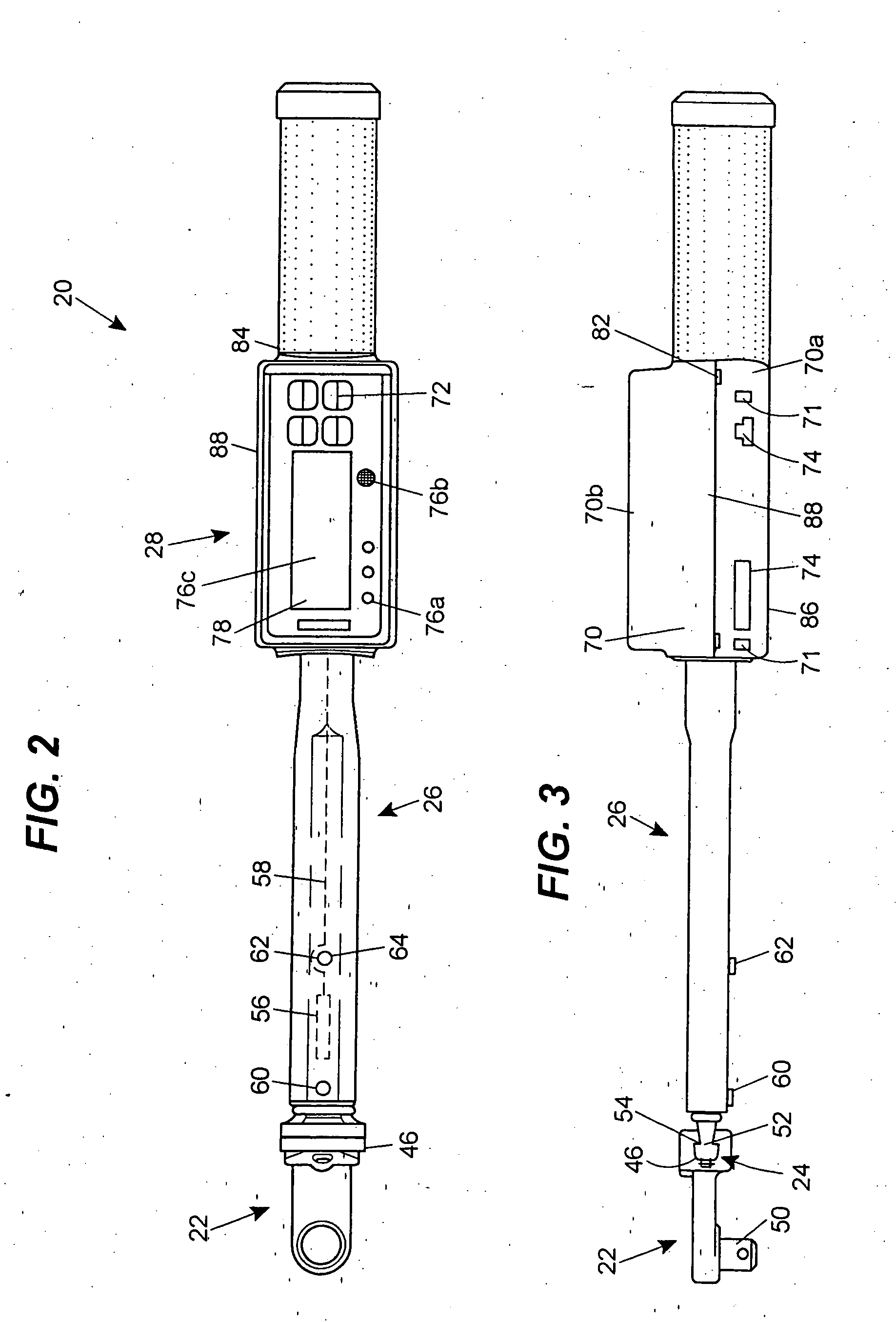
[0020] Turning now to the drawings, and with specific reference to FIG. 1, a torque wrench constructed in accordance with the teachings of the disclosure is generally referred to by reference numeral 20. As shown therein, the torque wrench 20 is of the type adapted to rotate a threaded fastener to a predetermined torque value. The torque wrench 20 may further be adapted to indicate the actual torque value, and may be adapted to indicate a torque range based on the actual torque value and the predetermined torque value. Such a high quality, accurate wrench is particularly applicable for use in tightly toleranced assembly processes including those of the automotive and aircraft industries. Moreover, while the torque wrench 20 is described and depicted as being a digital torque wrench, it is to be understood that its teachings could be employed for creating an analog output as well.

[0021] With reference to FIG. 7, a torque control system is depicted in accordance with the teachings of...


PUM


Abstract

A system for controlling torque related data is disclosed. The system may include one or more torque wrenches each having a first controller, and each being adapted to communicate with a second controller. Each torque wrench may further include a handle and a torquing tool. A torque sensor is disposed on each of the torque wrenches and is adapted to provide torque related data of a fastener to the first controller. The second controller is communicably coupled to the first controller and receives the torque data of the fastener.

Description

FIELD OF THE DISCLOSURE [0001] The disclosure generally relates to hand tools and, more particularly, relates to torque wrenches. BACKGROUND OF THE DISCLOSURE [0002] In many industrial applications, the tightening of threaded fasteners to a specific degree or torque is of extreme importance. For example, in the assembly of automobiles or aircraft, it is imperative that nuts, bolts, screws, lugs, and the like, are tightened to a pre-specified torque to ensure the resulting assembly functions properly not only at initial use, but over the long term. Moreover, it is not sufficient that the device simply be tightened as far as possible as this may result in stripping of the threads or vibrational problems in the resulting assembly. [0003] Accordingly, it has long been known to use torque wrenches for tightening such devices. Such wrenches are not only able to rotate and tighten the device, but also provide the user with some sort of indication as to the torque being applied. Such device...

Claims


Application Information

Patent Timeline
13 Oct 2005
Publication
US20050223856A1
IPC
B25B23/142; B25B23/144
CPC
B25B23/1425
Inventors
REYNERTSON, JOHN; GAUTHIER, JEROME M.