Extension lift truck modification

a technology for lifting trucks and extension lifts, applied in the direction of manufacturing tools, lifting devices, welding apparatuses, etc., can solve the problems of high cost, high cost of installation, and general exposure of products to accidental damage or theft risk,

Active Publication Date: 2005-10-13
LINCOLN GLOBAL INC
View PDF4 Cites 36 Cited by
  • Summary
  • Abstract
  • Description
  • Claims
  • Application Information

AI Technical Summary

Benefits of technology

[0007] The present invention contemplates a new and improved arc welder/lift system that resolves the above-referenced difficulties and othe

Problems solved by technology

Extra costs are thus incurred, and the products are generally exposed to the risk of accidental damage or theft.
Further, this means there are cumbersome leads hanging from the boom platforms down to the portable equipment, and, during operation, a welder or generator has to be moved every time the user needs to change position or powe

Method used


Image

  • Extension lift truck modification
  • Extension lift truck modification
  • Extension lift truck modification

Examples


Embodiment Construction

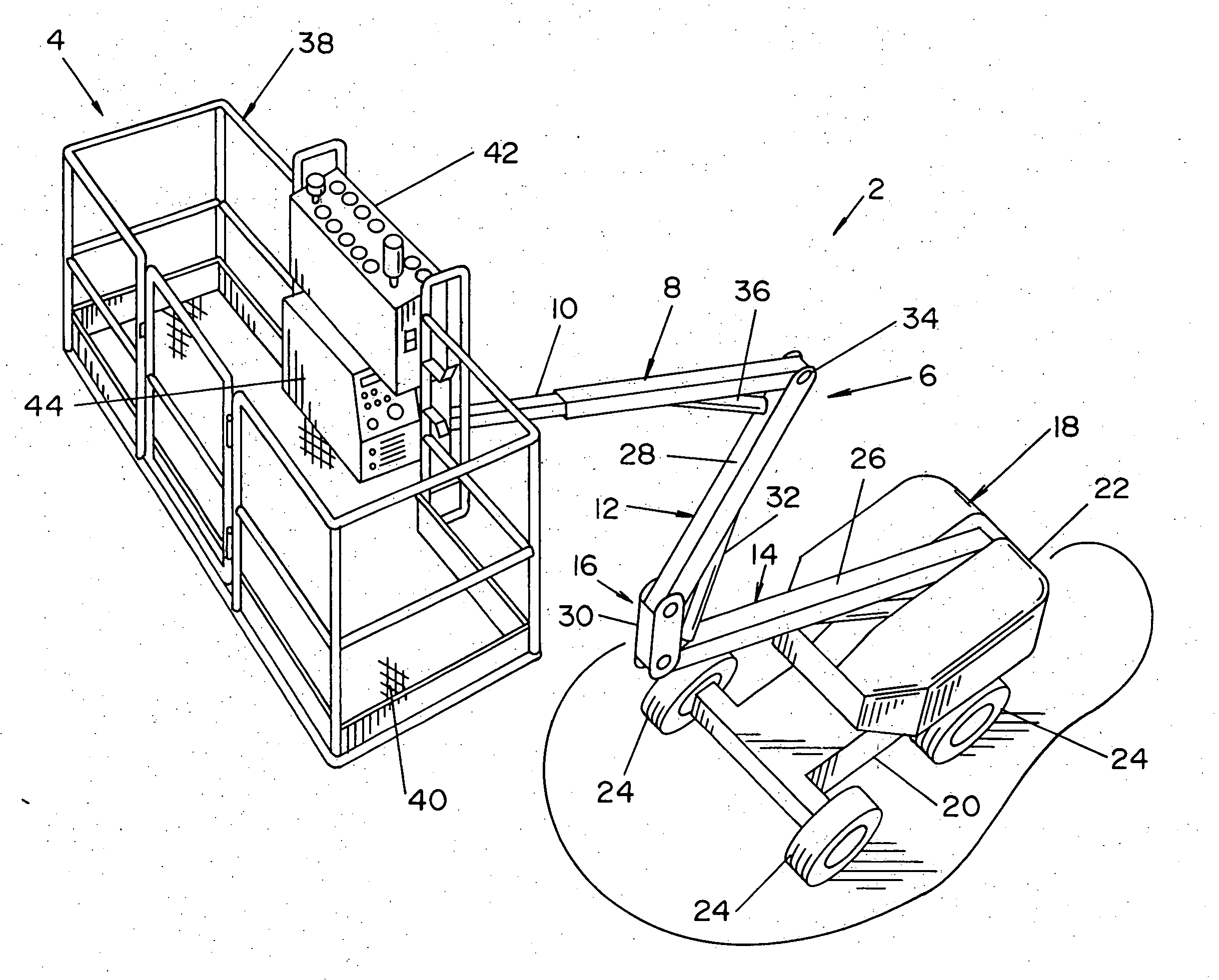
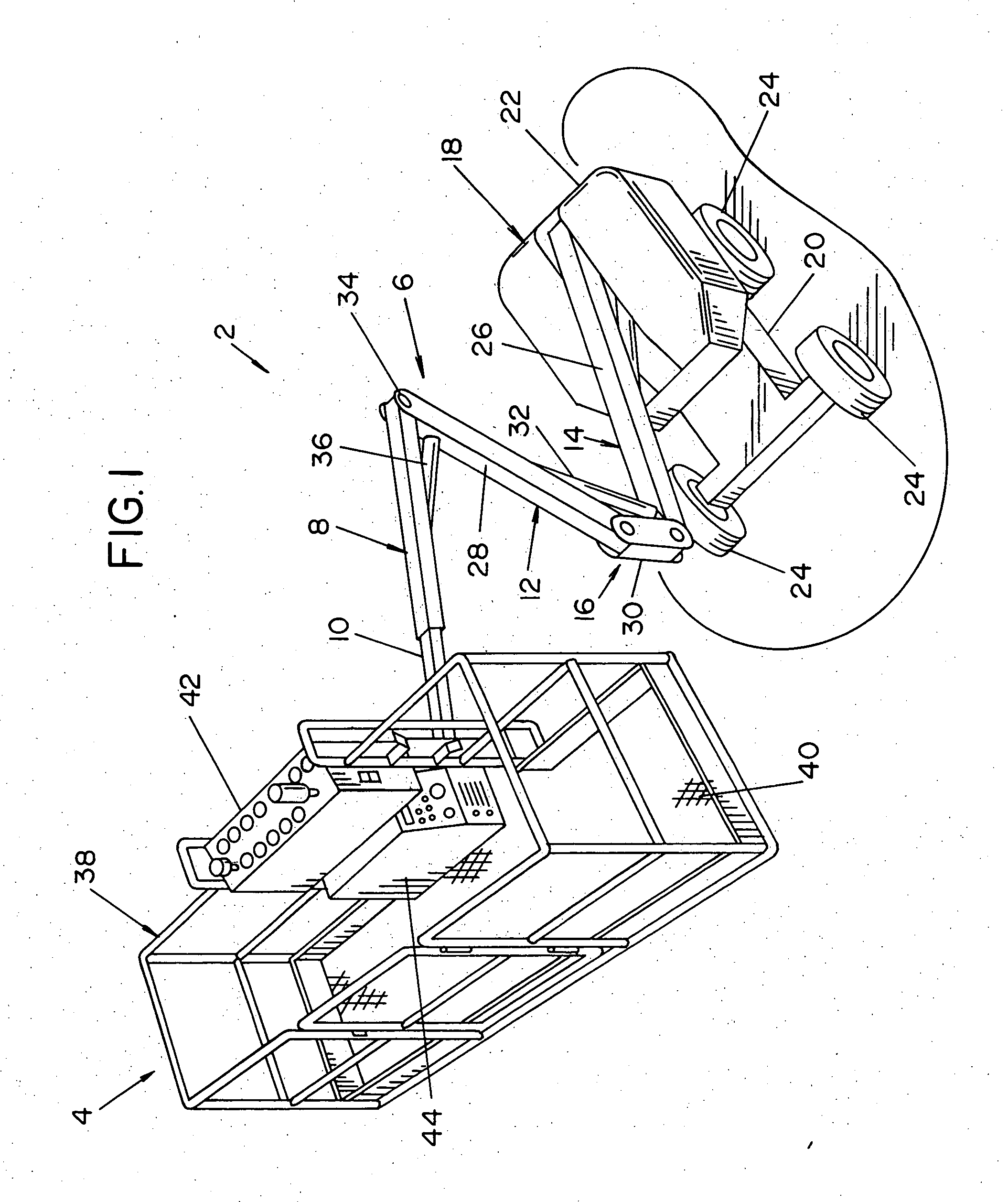
[0023] Referring now to the drawings wherein the showings are for the purpose of illustrating the preferred embodiment and its advantages only and not for the purpose of limiting same, with like numerals being used for like and corresponding parts of the various drawings, FIG. 1 is a perspective view of an arc welder / lift system 2. The arc welder / lift system 2 includes a personnel platform 4 attached to the load-receiving end of a three-section, Z-shaped articulating boom 6. The upper section 8 of the articulating boom 6 is attached to the personnel platform 4 and telescopes 10. The middle and lower sections 12 and 14 define a raising linkage 16. The raising linkage 16 extends from a turntable 18 that is mounted on a drive chassis 20. The turntable 18 and the drive chassis 20 form the base of the arc welder / lift system 2 shown.

[0024] Briefly described, the articulating boom 6 is designed such that it can extend upward, as shown in FIG. 1, or can be lowered into a stowed position (n...


PUM

PropertyMeasurementUnit
Electric potential / voltageaaaaaaaaaa
Frequencyaaaaaaaaaa
Poweraaaaaaaaaa

Abstract

An apparatus for welding, including a lift mechanism for lifting a personnel platform attached to an end of the lift mechanism, a drive system for moving the apparatus, where the drive system includes a DC power source, a set of controls mounted on the platform for controlling the drive system and the lift mechanism, and an electric arc welding system for creating a DC welding arc between an electrode and a workpiece, where the welding system is mounted on the personnel platform and powered by the DC power source.

Description

[0001] The present invention relates generally to the art of welding, and, more particularly, to an extension lift truck modification, wherein an electric arc welding system is incorporated into the personnel platform of a lift truck with a DC power source and is powered by the lift's DC power source. INCORPORATION BY REFERENCE [0002] The present invention relates to an electric arc welding system employing well known chopper technology. Many patents disclose chopper technology as used in arc welding. One such patent is Baker, U.S. Pat. No. 5,864,116, which is incorporated by reference herein as background information. This patent shows the architecture of a DC down chopper having a circuit for controlling the effective inductance between the down chopper and the welding operation. BACKGROUND OF THE INVENTION [0003] By way of background, many different types of lifts for positioning workers and material at various heights are presently in use. Lifts are used in many different types ...

Claims


Application Information

Patent Timeline
IPC IPC(8): B23K9/10B66F11/04
CPCB23K9/10B23K9/1006B66F11/04
Inventor STROPKI, JOHN M. JR.MATTHEWS, WILLIAM T.
Owner LINCOLN GLOBAL INC
Why Eureka
Try Eureka