Self-conforming screen

a screen and self-conform technology, applied in the direction of drilling pipes, drilling rods, borehole/well accessories, etc., can solve the problems of large annular space outside the screen, the risk of sticking the fixed swage, and the screen expansion technique as a replacemen

Inactive Publication Date: 2006-03-21
BAKER HUGHES HLDG LLC
View PDF34 Cites 132 Cited by
  • Summary
  • Abstract
  • Description
  • Claims
  • Application Information

AI Technical Summary

Benefits of technology

[0007]A screen that conforms to the borehole shape after expansion is disclosed. The screen comprises a compliant outer layer that takes the borehole shape on expansion. The outer layer is formed having holes to permit production flow. The material that is selected preferably swells with prolonged contact to well fluids to further close off annular gaps after expansion. In an alternative embodiment, the screen is not expanded and the swelling of the material alone closes off annular gaps. The outer sleeve is placed over the screen and the screen is placed on a base pipe and initially expanded from within the base pipe to secure the components of the screen assembly for running downhole, while minimizing or eliminating any welding among the layers. A variety of expansion tools can be used to expand the screen or screens downhole.

Problems solved by technology

Problems arose with the screen expansion technique as a replacement for gravel packing because of wellbore shape irregularities.
The problems were that a washout in the wellbore would still leave a large annular space outside the screen.
Conversely, a tight spot in the wellbore could create the risk of sticking the fixed swage.
On the other hand, if there was a void area, the same problem persisted in that the flexible swage had a finite outer dimension to which it would expand the screen.
Therefore, the use of flexible swages still left the problem of annular gaps outside the screen with a resulting undesired production of solids when the well was put on production from that zone.

Method used


Image

  • Self-conforming screen
  • Self-conforming screen
  • Self-conforming screen

Examples


Embodiment Construction

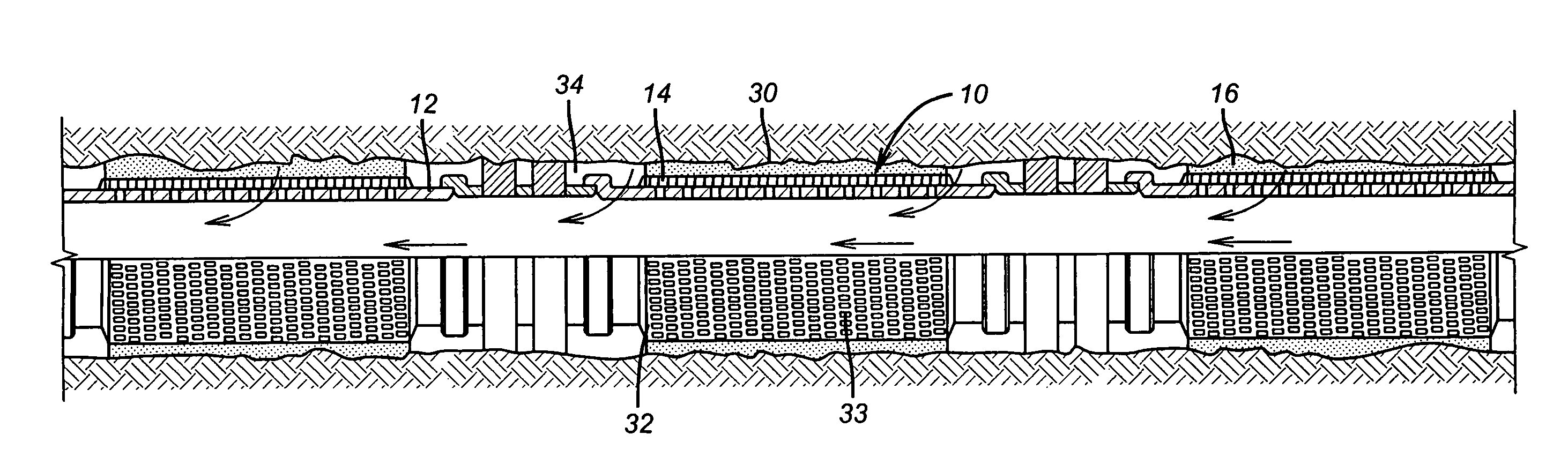
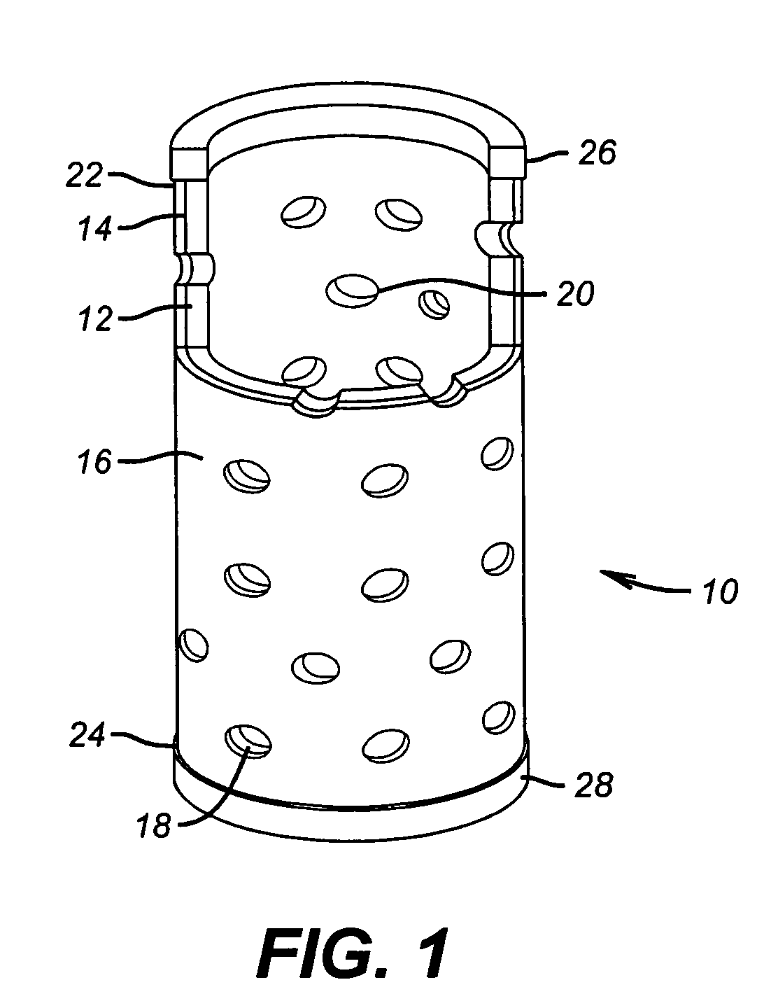
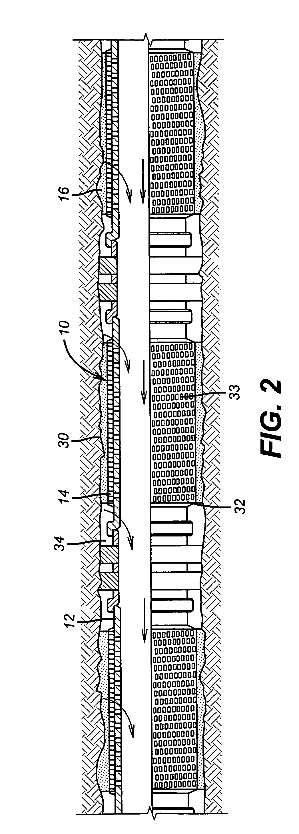
[0010]FIG. 1 illustrates a portion of a section of screen 10. It has a base pipe 12 over which is the screen 14 and over which is outer conforming layer 16. Layer 16 has a plurality of holes 18. The base pipe 12 also has holes 20. The actual filter material or screen 14 can be a mesh or a weave or other known filtration products. The conforming layer 16 is preferably soft so, that it will flow upon expansion of the screen 10. The preferred material is one that will swell when exposed to well fluids for an extended period of time. Three examples are nitrile, natural rubber, and AFLAS. In an alternative embodiment, the conforming layer 16 swells sufficiently after being run into the wellbore, to contact the wellbore, without expansion of the screen 10. Shown schematically at the ends 22 and 24 of screen 10 are stop rings 26 and 28. These stop rings will contain the conforming layer 16 upon expansion of screen 10 against running longitudinally in an annular space outside screen 10 afte...


PUM


Abstract

A screen that conforms to the borehole shape after expansion is disclosed. The screen comprises a compliant outer layer that takes the borehole shape on expansion. The outer layer is formed having holes to permit production flow. The material that is selected preferably swells with prolonged contact to well fluids to further close off annular gaps after expansion. In an alternative embodiment, the screen is not expanded and the swelling of the material alone closes off annular gaps. The outer sleeve is placed over the screen and the screen is placed on a base pipe and initially expanded from within the base pipe to secure the components of the screen assembly for running downhole, while minimizing or eliminating any welding among the layers. A variety of expansion tools can be used to expand the screen or screens downhole.

Description

PRIORITY INFORMATION[0001]This application is a continuation of U.S. patent application Ser. No. 10 / 226,941, filed on Aug. 23, 2002.FIELD OF THE INVENTION[0002]The field of this invention is downhole screens and more particularly those that can be expanded in open hole to close off an irregularly shaped borehole.BACKGROUND OF THE INVENTION[0003]In the past sand control methods have been dominated by gravel packing outside of downhole screens. The idea was to fill the annular space outside the screen with sand to prevent the production of undesirable solids from the formation. More recently, with the advent of tubular expansion technology, it was thought that the need for gravel packing could be eliminated if a screen or screens could be expanded in place to eliminate the surrounding annular space that had heretofore been packed with sand. Problems arose with the screen expansion technique as a replacement for gravel packing because of wellbore shape irregularities. A fixed swage wou...

Claims


Application Information

Patent Timeline
Patent Type & Authority Patents(United States)
IPC IPC(8): E21B43/08E21B43/10
CPCE21B43/086E21B43/108E21B43/103
Inventor RICHARD, BENNETT M.
Owner BAKER HUGHES HLDG LLC
Why Eureka
Try Eureka