Water-permeable concrete pad and form

a concrete pad and water-permeable technology, applied in the field of concrete pads, can solve the problems of increasing the cost of concrete pads, and reducing the service life of concrete pads,

Inactive Publication Date: 2005-10-13
HOBBS GEORGE J
View PDF48 Cites 28 Cited by
  • Summary
  • Abstract
  • Description
  • Claims
  • Application Information

AI Technical Summary

Benefits of technology

[0020] After the concrete has cured, the conduit caps are removed. The resultant concrete pad has all of the attributes of a conventional concrete pad in terms of durability and support for objects placed on the pad. However, due to the conduits, water t

Problems solved by technology

One disadvantage of concrete pads is the fact that water impinging on the pad, e.g., rainwater, is prevented from absorption into the soil beneath the pad, resulting in runoff that can cause flooding and soil erosion.
This approach is considerably more expensive than pouring a single concrete pad, and p

Method used


Image

  • Water-permeable concrete pad and form
  • Water-permeable concrete pad and form
  • Water-permeable concrete pad and form

Examples


Embodiment Construction

[0029] In the following description, terms such as horizontal, upright, vertical, above, below, beneath, and the like, are used solely for the purpose of clarity in illustrating the invention, and should not be taken as words of limitation. The drawings are for the purpose of illustrating the invention and are not intended to be to scale.

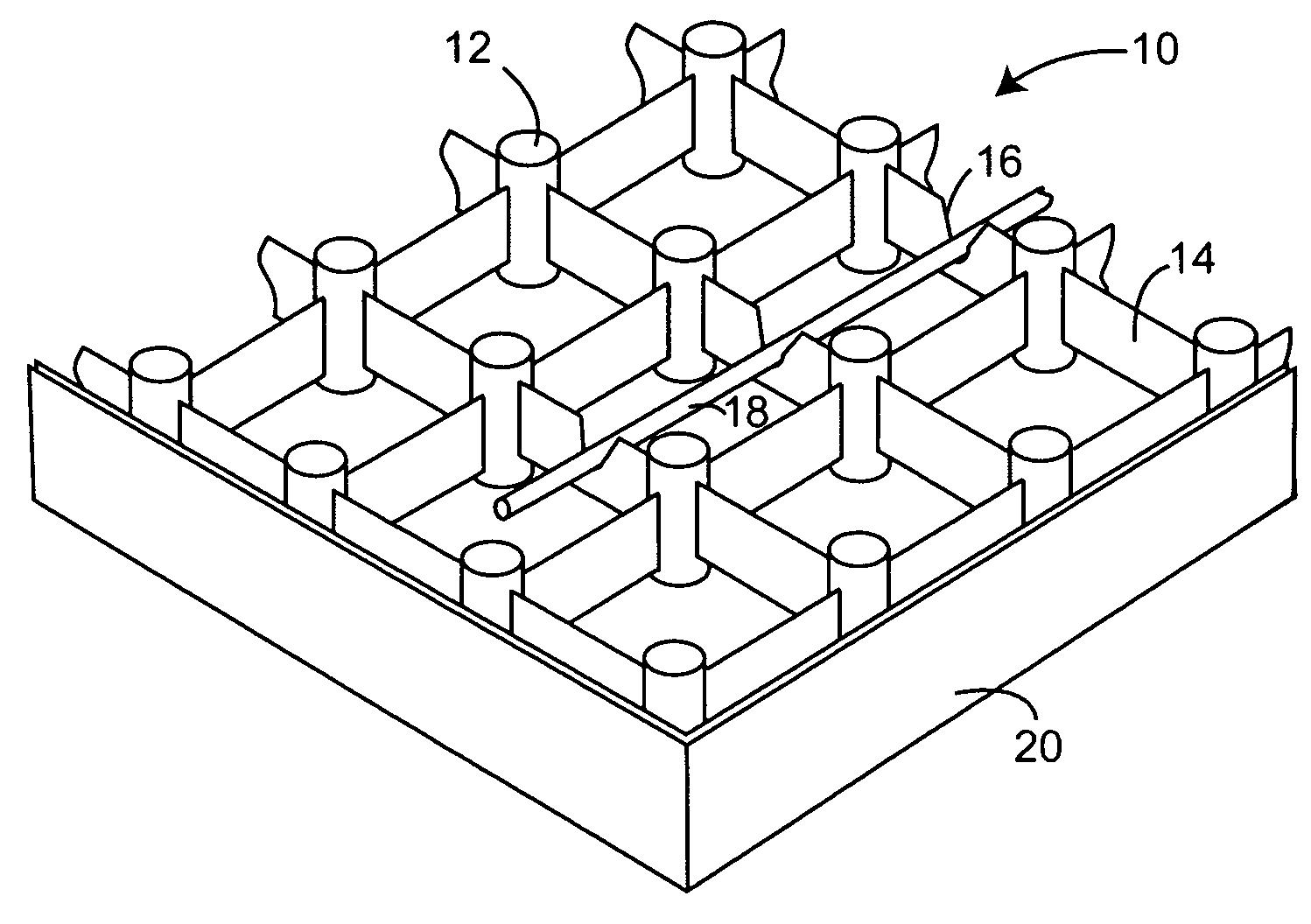
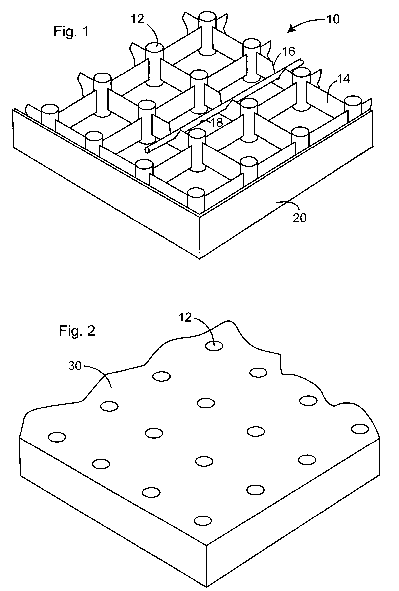
[0030] As best shown in FIG. 1, a preferred embodiment of form, generally 10, is comprised of a plurality of vertical conduits 12 joined by spacers 14 in a rectangular array. Some of spacers 14 may include attachments 16 for positioning of rebar 18. In the embodiment shown, attachment 16 is a V-shaped slot having a lower end approximately one-half the distance between the upper and lower surfaces of form 10. As shown, form 10 is enclosed within a temporary frame 20, which is removed after the poured concrete has cured.

[0031]FIG. 2 illustrates a concrete pad, generally 30, poured using the form illustrated in FIG. 1. The upper ends of conduits 12 o...


PUM

PropertyMeasurementUnit
Lengthaaaaaaaaaa
Thicknessaaaaaaaaaa
Shapeaaaaaaaaaa

Abstract

A concrete pad with drainage holes is created using an in-situ form with a plurality of spaced, vertically aligned conduits having upper ends with removable caps and spacers connecting the conduits. The form is horizontally positioned at the area where the pad is to be created and concrete is poured into the form until the upper surface of the concrete is in a plane with the upper ends of the conduits. After the concrete has cured, the caps are removed to permit water to flow from the top of the pad through the conduits for drainage into the soil beneath the pad.

Description

BACKGROUND OF THE INVENTION [0001] (1) Field of the Invention [0002] The present invention relates to concrete pads having drainage holes, and in particular to concrete pads made using a form that includes a plurality of spaced, vertically aligned conduits joined by spacers, and having removable caps covering their upper ends. [0003] (2) Description of the Prior Art [0004] Concrete pads, i.e., a layer of poured concrete having a given length, width and thickness, are highly durable and are widely used for a variety of applications including walkways, driveways, and the like. Normally, concrete pads are formed by preparing the surface on which the pad is to be poured, and then constructing a removable form or frame about the periphery of the area. [0005] The interior of the form is then filled with a pourable concrete mix and the upper surface of the poured concrete is leveled with the upper surface of the form, normally by drawing a screed supported by the form over the concrete to ...

Claims


Application Information

Patent Timeline
IPC IPC(8): E04F15/12E01C11/24E01C11/22E01C5/08E01C9/00E01C13/02
CPCE01C5/08E01C9/001E01C11/225E04F15/12
Inventor HOBBS, GEORGE J.
Owner HOBBS GEORGE J
Why Eureka
Try Eureka