Measuring system

a measuring system and measuring device technology, applied in the field of measuring devices, can solve the problems of affecting the accuracy of the tool center point, affecting the accuracy of the tool or the touch-up pin, and no publications describing a technique capable of solving these problems by a simplified method, etc., to achieve the effect of eliminating the variation of the position of the tool center point, high accuracy, and steady and safe measuremen

Active Publication Date: 2005-10-13
FANUC LTD
View PDF3 Cites 59 Cited by
  • Summary
  • Abstract
  • Description
  • Claims
  • Application Information

AI Technical Summary

Benefits of technology

[0020] This invention can eliminate the variations of the position of the tool center point depending on the posture of the robot or the skill of the operator in touching the tool center point to the touch-up pin. Also, the error of the position of the tool center point which otherwise might be caused by visual alignment is eliminated. Further, the noncontact measurement can eliminate an accident by contact which otherwise might be caused in touch-up operation. These advantages make possible a highly accurate, steady and safe measurement.
[0021] In addition, the view line of the camera can b

Problems solved by technology

This method, however, poses the following problems: (1) As described above, at the time of the touch-up operation, the robot is jogged while the tool center point of the robot is aligned to coincide with the forward end of the touch-up pin.
(2) Also, this positioning operation is performed visually, and therefore even a skilled operator can produce only a limited accuracy.
(3

Method used


Image

  • Measuring system
  • Measuring system
  • Measuring system

Examples


Embodiment Construction

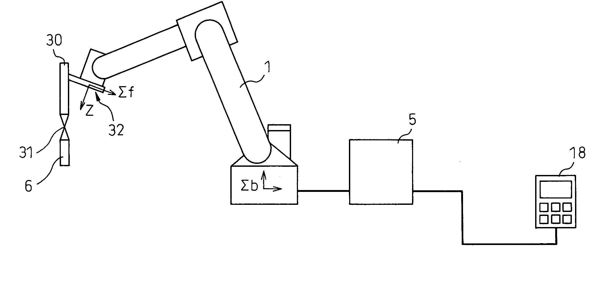
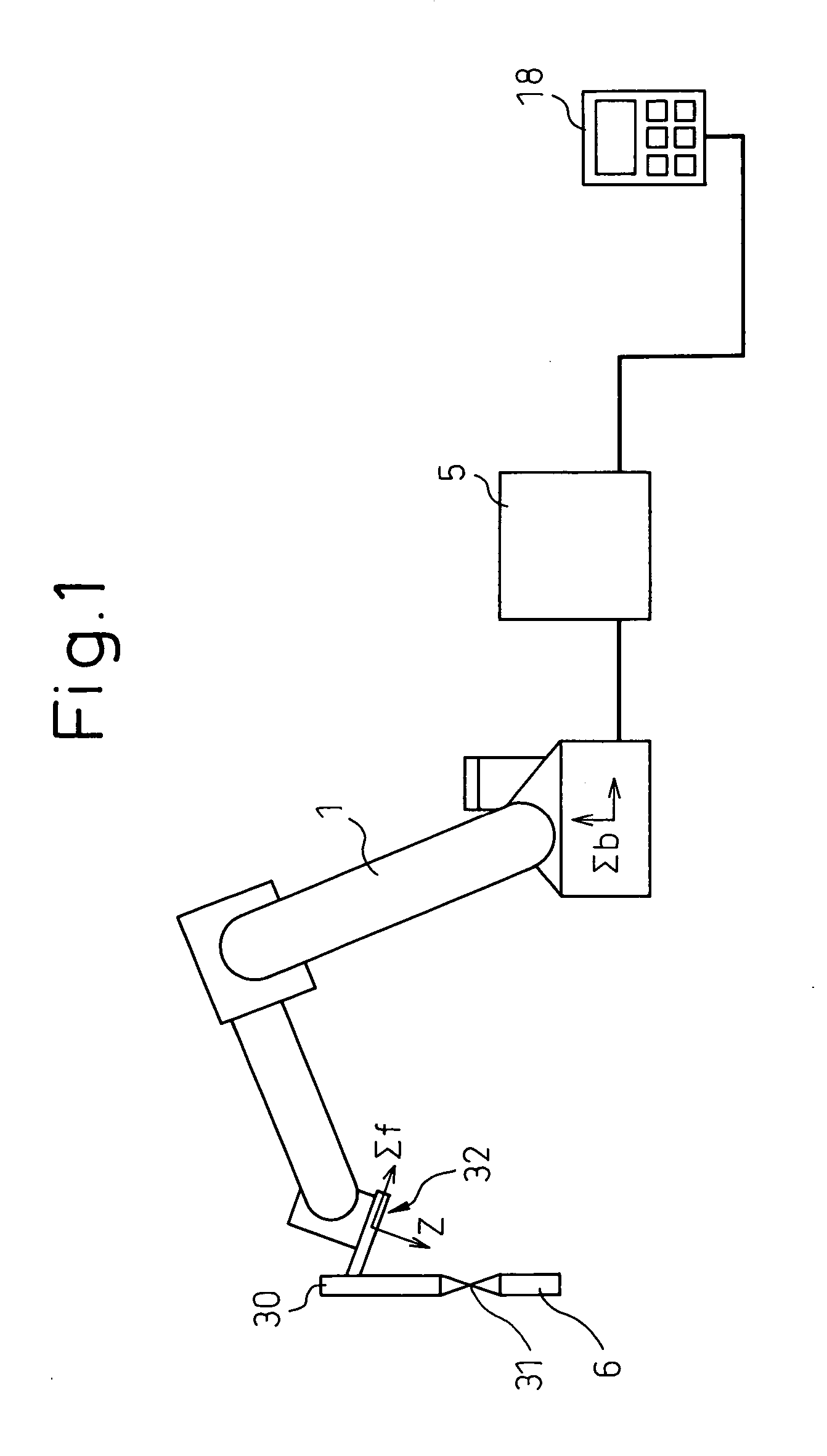
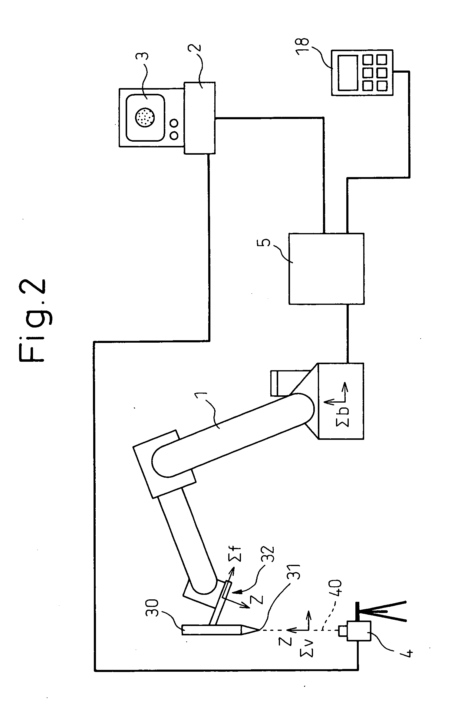
[0036] Embodiments of the invention are explained below with reference to FIGS. 2 to 10 sequentially. First, FIG. 2 is a schematic diagram showing a general configuration of an embodiment of the invention. As shown in FIG. 2, a robot 1 is connected to a robot control unit 5 for controlling the robot 1, and a tool 30 is mounted at the forward end (tool mounting surface 32) of the arm of the robot 1. A robot coordinate system Σb fixed on the robot base and a mechanical interface coordinate system Σf fixed on the tool mounting surface 32 are set in the robot 1. The position and posture (current position) of the origin of the mechanical interface coordinate system can be known at any time in the robot control unit 5. Also, a well-known teaching operation panel 18 having manual operation keys is connected to the robot control unit 5, and the robot 1 can be manipulated by the operator through the manual operation keys.

[0037] The robot 1 is a well-known typical robot, and the robot contro...


PUM


Abstract

The image of a tool center point (31) caught by a camera (light-receiving device) 4 from two initial positions is moved to a predetermined point, by a predetermined point moving process, at the center of a light-receiving surface thereby to acquire robot positions (Qf1, Qf2), based on which the direction of the view line (40) is determined. Next, the robot is moved to the position where the position (Qf1) is rotated by 180 degrees around the Z axis of a coordinate system (Σv1) thereby to execute the predetermined point moving process. After rotational movement, a robot position (Qf3) is acquired. The midpoint between the position (Qf1) and the position (Qf3) is determined as the origin of a coordinate system (Σv2). Using the position and the posture of the view line (40), the position of the tool center point (31) is determined. Thus, the position of the tool center point with respect to the tool mounting surface can be determined using a fixed light-receiving device. By additionally measuring two points at known relative positions from the tool center point, the tool posture as well as the position of the tool center point can be determined.

Description

BACKGROUND OF THE INVENTION [0001] 1. Field of the Invention [0002] The present invention relates to a measuring system for measuring the position of a tool center point (TCP) with respect to the tool mounting surface of a tool mounted at the forward end of an arm of a robot or, in particular, to a measuring system for measuring the position of the tool center point with respect to the tool mounting surface by combining the robot with a light receiving device such as a camera or a PSD (position sensing detector). [0003] 2. Description of the Related Art [0004] A method to measure the position of the tool center point with respect to the tool mounting surface of a robot using the three-point touch-up or the six-point touch-up capability is known. FIG. 1 shows a typical arrangement used for application of this method. As shown in FIG. 1, the robot 1 is connected to a robot control unit 5 for controlling the robot 1, and a tool 30 is mounted at the forward end of the arm of the robot 1...

Claims


Application Information

Patent Timeline
IPC IPC(8): G01B11/00B25J9/16G01B11/26G05B19/401
CPCB25J9/1692G05B2219/39008G05B2219/39394G05B2219/40607
Inventor BAN, KAZUNORIYAMADA, MAKOTO
Owner FANUC LTD
Why Eureka
Try Eureka