Congestion control system

a control system and control system technology, applied in the field of computer networks, can solve problems such as network congestion, ) exceed the capacity of the network, and cannot be achieved by a pure window control mechanism

Active Publication Date: 2005-10-13
VALTRUS INNOVATIONS LTD +1
View PDF5 Cites 47 Cited by
  • Summary
  • Abstract
  • Description
  • Claims
  • Application Information

AI Technical Summary

Problems solved by technology

Network congestion arises when traffic sent or injected into a communications network (i.e., the number of injected packets or bytes per unit of time) exceeds the capacity of the network.
This is not possible to achieve by a pure window control mechanism since the minimum window size is the ...

Method used


Image

  • Congestion control system
  • Congestion control system
  • Congestion control system

Examples


Embodiment Construction

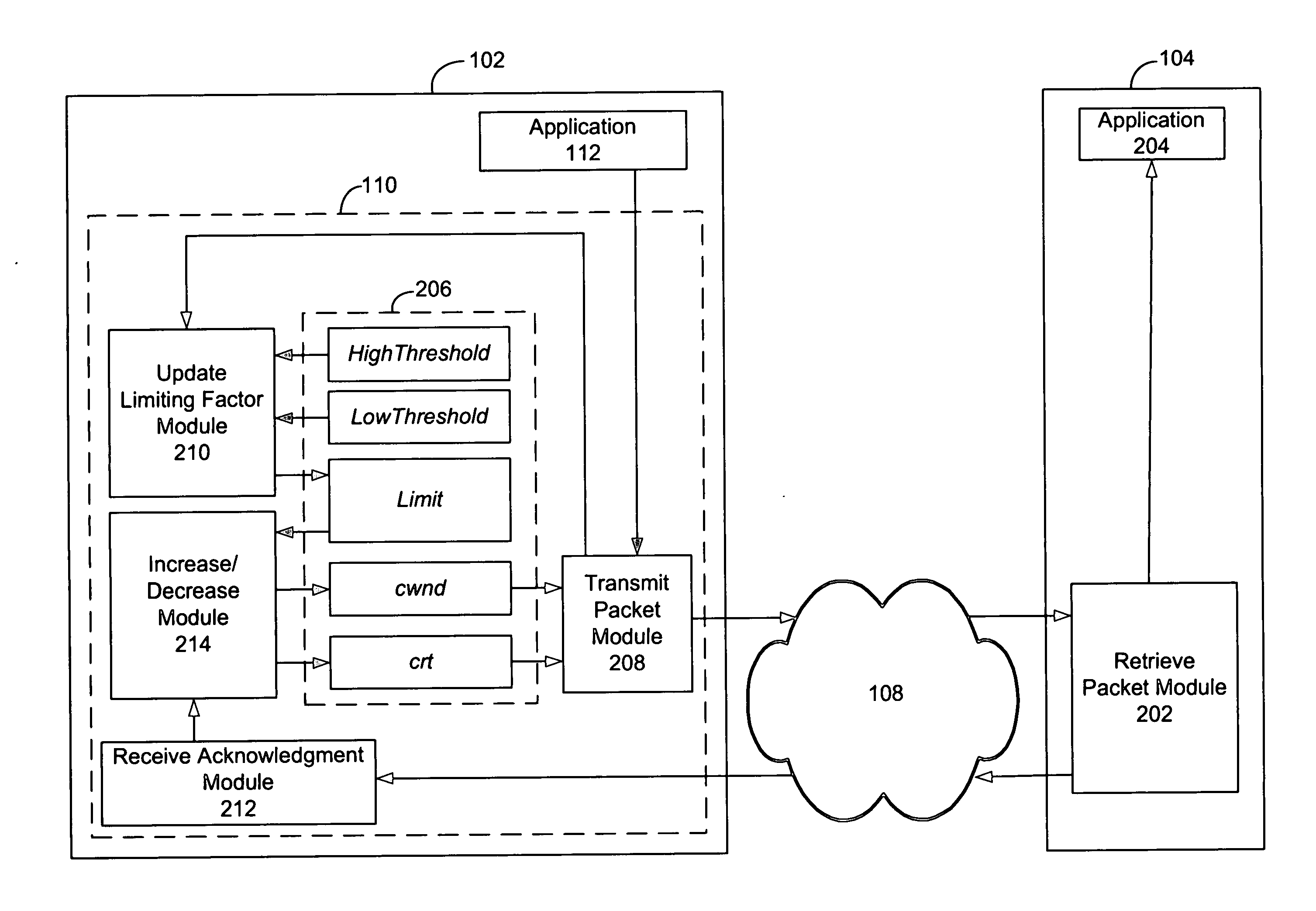
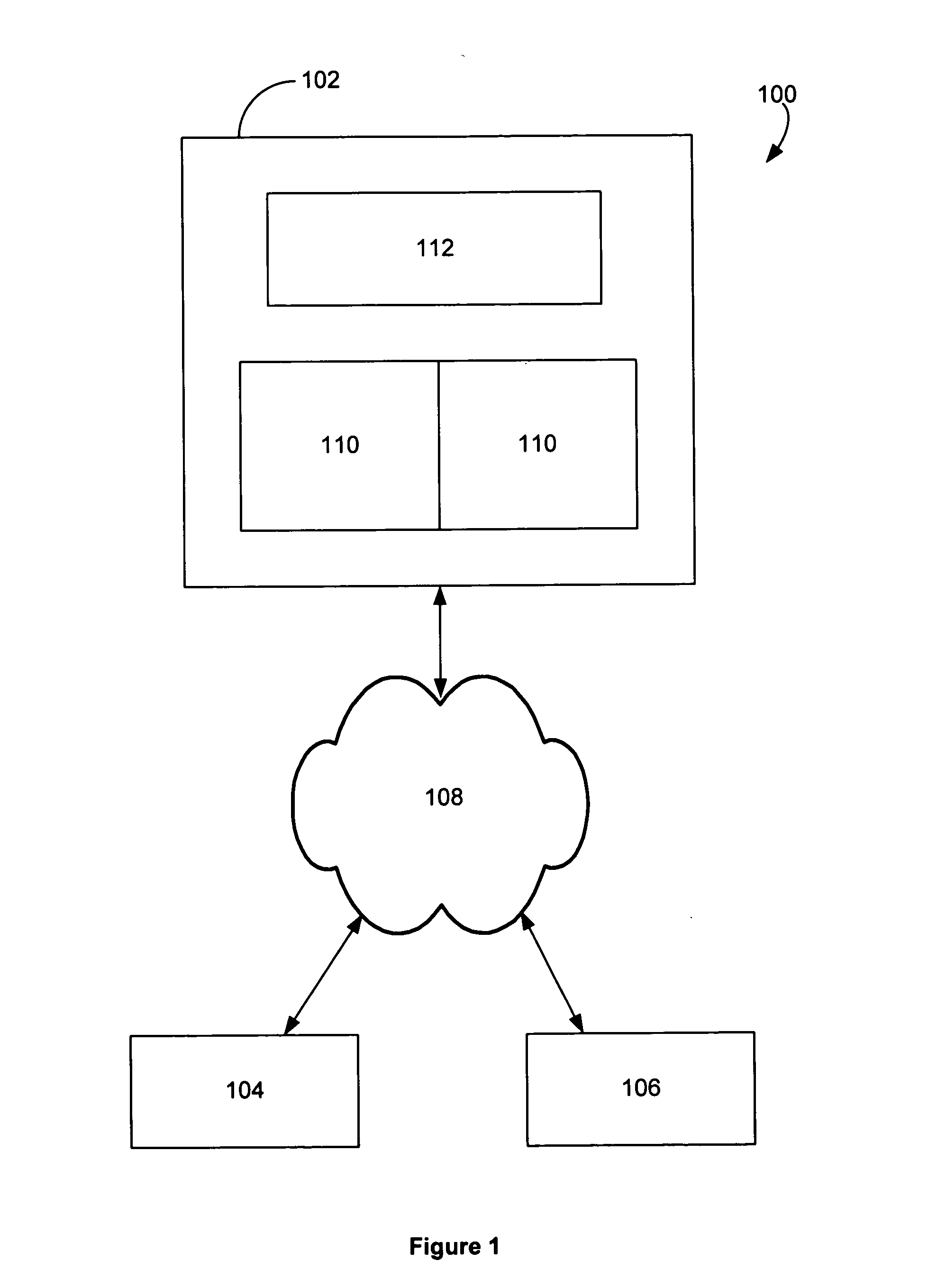
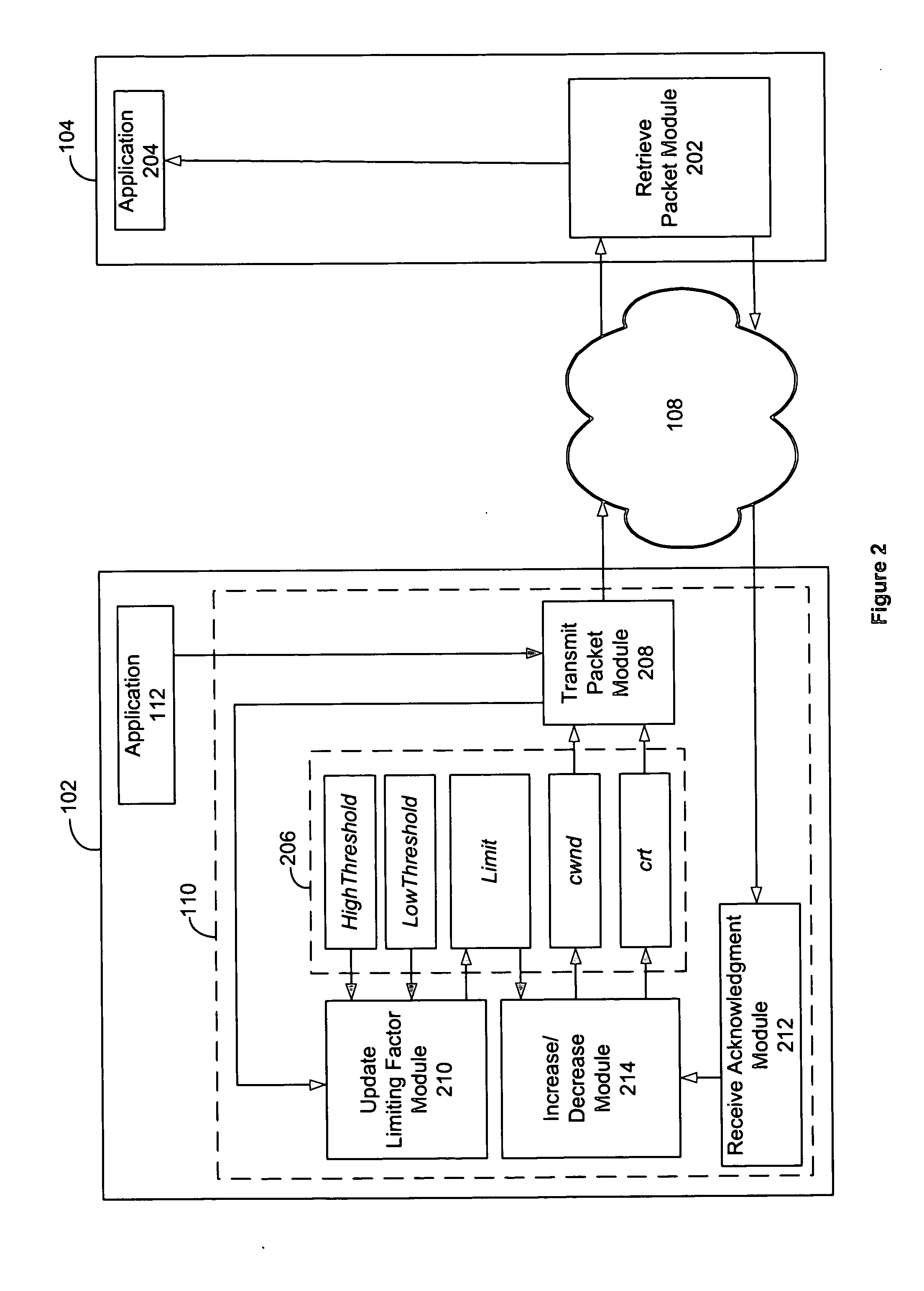
[0025] A communications system 100, as shown in FIG. 1, includes a sender node 102 (e.g., a computer, I / O device or a network interface that connects a computer or I / O device to a network) that communicates with one or more receiver nodes 104, 106 via a communications network 108. The sender node 102 includes one or more implementations or instances of a congestion control system 110. Each congestion control system 110 facilitates transmission of a stream of data (or flow) from the sender node 102 to a single receiver node 104, as shown in FIG. 2. The congestion control system 110 works with an underlying reliable transport protocol that uses ACK packets to acknowledge successful delivery of data packets to the destination.

[0026] The congestion control system 110 shown in FIG. 2 receives data from an application 112 executed on the sender node 102, or on a separate node communicating with the sender node 102, and transmits data as packets to a receiver node 104. The receive packet ...


PUM


Abstract

According to the present invention, there is provided a method for controlling congestion in a communications network, the method including receiving congestion feedback data relating to said network, adjusting at least one of a window limit and a rate limit based on said congestion feedback data and injecting data packets onto said network according to said window limit and said rate limit.

Description

FIELD OF THE INVENTION [0001] The present invention relates generally to computer networks and in particular, to a system and process for controlling network congestion in a communications network. BACKGROUND [0002] Network congestion arises when traffic sent or injected into a communications network (i.e., the number of injected packets or bytes per unit of time) exceeds the capacity of the network. Congestion causes the throughput of useful data traffic (i.e., traffic that reaches its destination) to be reduced because when the network is congested, packets hold onto network resources for longer times and / or network resources are consumed by packets that are later discarded. Network congestion is typically controlled by mechanisms for detecting congestion and by adjusting the amount of data traffic injected at the end nodes. [0003] Congestion detection processes can be implemented at endpoints or at internal components of the network, such as switches or routers. As described in V...

Claims


Application Information

Patent Timeline
IPC IPC(8): H04L1/00H04L12/56
CPCH04L47/10H04L47/29H04L47/27H04L47/26
Inventor SANTOS, JOSE RENATOTURNER, YOSHIOJANAKIRAMAN, GOPALAKRISHNAN
Owner VALTRUS INNOVATIONS LTD
Why Eureka
Try Eureka