Check patentability & draft patents in minutes with Patsnap Eureka AI!

Wheel bearing apparatus incorporated with a wheel speed detecting apparatus

a technology of speed detection and wheel bearings, which is applied in mechanical devices, instruments, transportation and packaging, etc., can solve the problems of inability to prevent ingress of foreign matter, such as magnetic powder, into the space between the magnetic encoders, and achieve the effect of improving the detection reliability of the wheel rotation speed

Inactive Publication Date: 2005-10-13
NTN CORP
View PDF3 Cites 25 Cited by
  • Summary
  • Abstract
  • Description
  • Claims
  • Application Information

AI Technical Summary

Benefits of technology

[0022] A wheel bearing apparatus incorporating a wheel speed detecting apparatus of the present invention comprises an outer member with a body and an integrally formed mount flange. Double row outer raceway surfaces are formed on the inner circumferential surface of the outer member. An inner member includes a wheel hub with an integrally formed wheel mounting flange at one end. A cylindrical portion axially extends from the wheel mounting flange. An inner ring is fitted on the cylindrical portion of the wheel hub. Double row inner raceway surfaces are formed on the outer circumferential surfaces of the wheel hub and inner ring, respectively, opposite to the double row outer raceway surfaces. Double row rolling elements are rotatably arranged between the outer and inner raceway surfaces. An encoder is mounted on the outer circumferential surface of the inner ring. An annular sensor holder is arranged on the end of the outer member opposite to the encoder. A wheel speed detecting sensor is molded integrally with the sensor holder and arranged opposite to the encoder, via a predetermined radial gap. The encoder has an annular ring configuration and its characteristics alternately and equidistantly vary along its circumferential direction. A seal is arranged at the inboard side of the encoder. The seal includes first and second annular sealing plates mounted on the sensor holder and the inner ring, respectively, and opposite toward each other. The encoder is mounted integrally on the second sealing plate. Accordingly, it is possible to prevent ingress of foreign matter, such as magnetic powder, into a space between the magnetic encoder and the detecting portion of the wheel speed sensor from the outside of the bearing apparatus although before the stem portion of the outer joint member is inserted into the wheel hub including a course in which the bearing apparatus is transferred to an assemble line of a manufacturer of automobiles and also under severe circumstances in real running of a vehicle. Thus, it is also possible to improve the detection reliability of the wheel rotation speed.
[0023] Another wheel bearing apparatus incorporating with a wheel speed detecting apparatus of the present invention comprises an outer member with an integrally formed body mounting flange. Double row outer raceway surfaces are formed on the inner circumferential surface of the outer member. An inner member includes a wheel hub with an integrally formed wheel mounting flange at one end. A cylindrical portion axially extends from the wheel mounting flange. An inner ring is fitted on the cylindrical portion of the wheel hub. Double row inner raceway surfaces are formed on the outer circumferential surfaces of the wheel hub and inner ring, respectively, opposite to the double row outer raceway surfaces. Double row rolling elements are rotatably arranged between the outer and inner raceway surfaces. An encoder is mounted on the outer circumferential surface of the inner ring. An annular sensor holder is arranged on the end of the outer member opposite to the encoder. A wheel rotation speed sensor is integrally molded with the sensor holder and arranged opposite to the encoder, via a predetermined radial gap. The encoder has an annular plate configuration and its characteristics alternately and equidistantly vary along its circumferential direction. A seal is arranged at the inboard side of the encoder via the sensor holder. The seal includes first and second annular sealing plates mounted on the sensor holder and the inner ring, respectively, and opposite toward each other. Accordingly it is possible to prevent ingress of foreign matter, such as magnetic powder, into a space between the magnetic encoder and the detecting portion of the wheel speed sensor from the outside of the bearing apparatus.
[0024] A wheel bearing apparatus incorporating with a wheel speed detecting apparatus comprises an outer member with an integrally formed body mounting flange. Double row outer raceway surfaces are formed on the inner circumferential surface of the outer member. An inner member includes a wheel hub with an integrally mounted wheel mounting flange at one end. A cylindrical portion axially extends from the wheel mounting flange. An inner ring is fitted on the cylindrical portion of the wheel hub. Double row inner raceway surfaces are formed on the outer circumferential surfaces of the wheel hub and inner ring, respectively, opposite to the double row outer raceway surfaces. Double row rolling elements are rotatably arranged between the outer and inner raceway surfaces. An encoder is mounted on the outer circumferential surface of the inner ring. An annular sensor holder is arranged on the end of the outer member opposite to the encoder. A wheel speed detecting sensor is integrally molded with the sensor holder and arranged opposite to the encoder, via a predetermined axial gap. The encoder has an annular ring configuration and is formed as a magnetic encoder. Magnetic poles, N and S of magnetic powder, are arranged along its circumferential direction. A seal is arranged at the inboard side of the encoder. The seal includes first and second annular sealing plates mounted on the sensor holder and the inner ring, respectively, and opposite toward each other. The encoder is mounted on the second sealing plate.
[0025] Further areas of applicability of the present invention will become apparent from the detailed description provided hereinafter. It should be understood that the detailed description and specific examples, while indicating the preferred embodiment of the invention, are intended for purposes of illustration only and are not intended to limit the scope of the invention.

Problems solved by technology

However, although the wheel bearing apparatus with the incorporated wheel speed detecting apparatus of the prior art has a superior effect mentioned above, it is impossible to prevent ingress of foreign matter, such as magnetic powder, into a space between the magnetic encoder 64 and the detecting portion of the wheel speed sensor 70 from the outside of the bearing apparatus under severe circumstances during real running of the vehicle.

Method used


Image

  • Wheel bearing apparatus incorporated with a wheel speed detecting apparatus
  • Wheel bearing apparatus incorporated with a wheel speed detecting apparatus
  • Wheel bearing apparatus incorporated with a wheel speed detecting apparatus

Examples


first embodiment

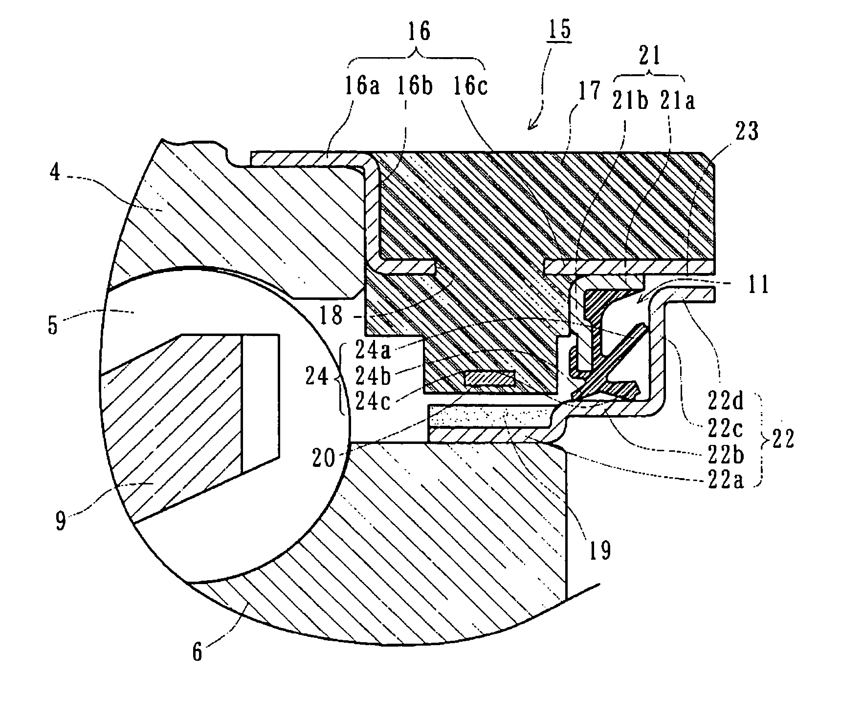
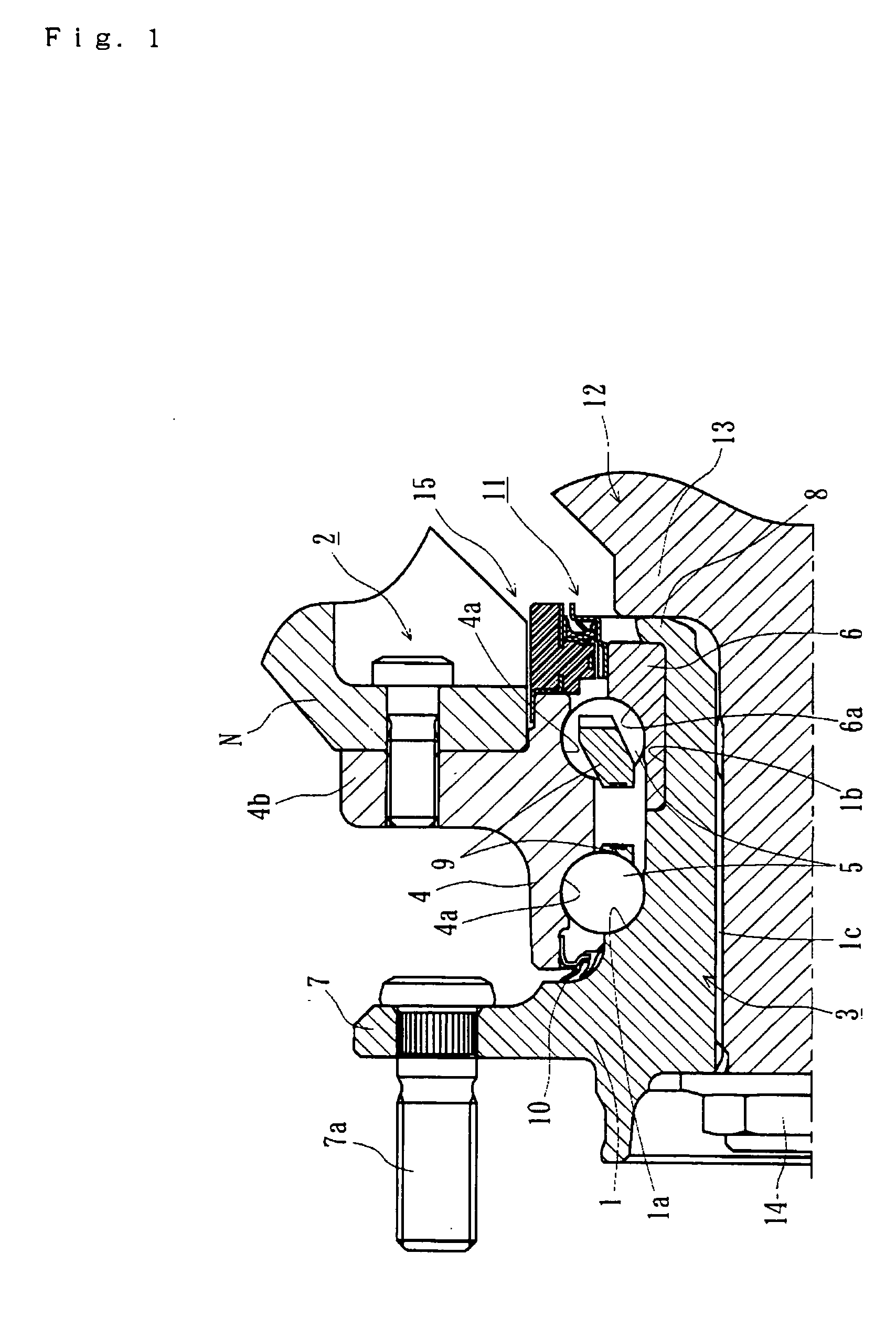
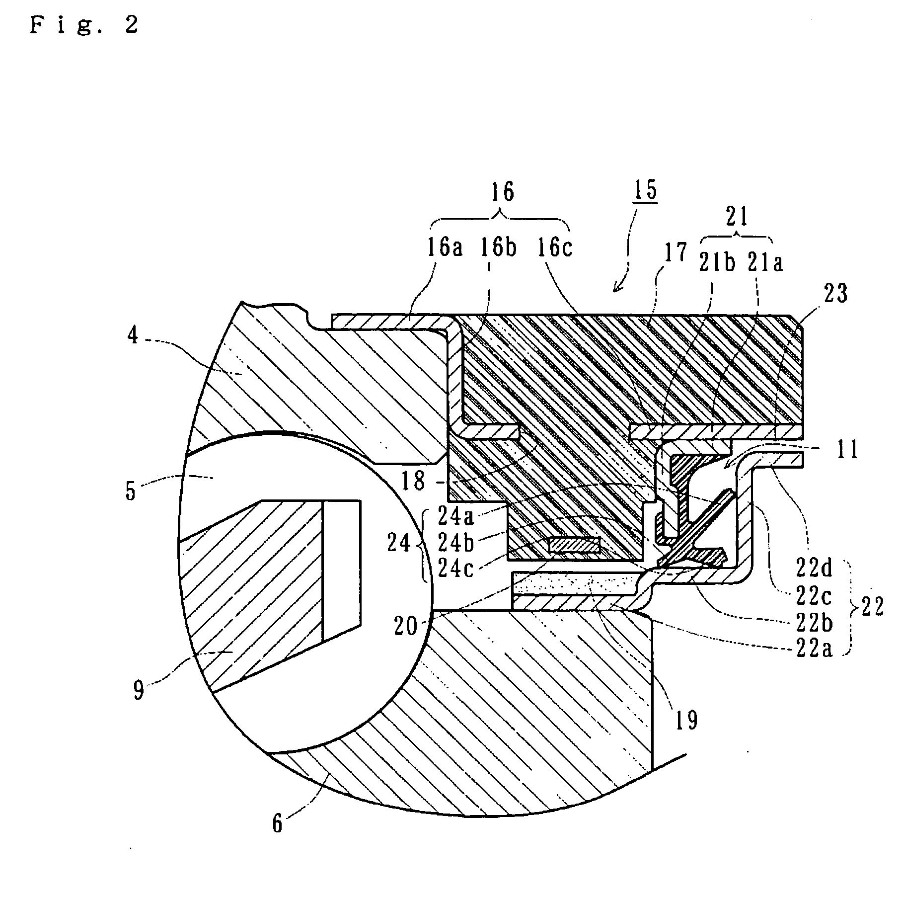
[0036]FIG. 1 is a longitudinal-section view of a first embodiment of a wheel bearing apparatus incorporating a wheel speed detecting apparatus of the present invention. FIG. 2 is a partially enlarged longitudinal-section view of FIG. 1. In the description of the present invention, an outer side of a bearing apparatus, when mounted on a vehicle, is referred to as “outboard” side (the left side in a drawing), and an inner side of a bearing apparatus, when it is mounted on a vehicle, is referred to as “inboard” side (the right side in a drawing).

[0037] The wheel bearing apparatus incorporated with a wheel speed detecting apparatus of the present invention is for a driving wheel. A wheel hub 1 and a double row rolling bearing 2 are formed as a unit arrangement and is a so-called “third generation”.

[0038] The double row rolling bearing 2 includes an outer member 4, an inner member 3, and double row rolling elements (balls) 5 and 5. The outer member 4 is made of medium carbon steel such...


PUM


Abstract

A wheel bearing apparatus incorporating a wheel speed detecting apparatus has an outer member (4) with an integrally formed body mounting flange (4b) and double row outer raceway surfaces (4a) formed on the inner circumferential surface of the outer member (4). An inner member (3) includes a wheel hub (1) with an integrally formed wheel mounting flange (7) at one end. A cylindrical portion (1b) axially extends from the wheel mounting flange (7). An inner ring (6) is fitted on the cylindrical portion (1b) of the wheel hub (1). Double row inner raceway surfaces (1a, 6a) are formed on the outer circumferential surfaces of the wheel hub (1) and inner ring (6), respectively opposite to the double row outer raceway surfaces (4a). Double row rolling elements (5) are rotatably arranged between the outer and inner raceway surfaces (4a; 1a, 6a). An encoder (19) is mounted on the outer circumferential surface of the inner ring (6). An annular sensor holder (15) is arranged on the end of the outer member (4) opposite to the encoder (19). A wheel speed detecting sensor (20) is integrally molded with the sensor holder (15) and arranged opposite to the encoder (19), via a predetermined radial gap. The encoder (19) has an annular ring configuration and its characteristics alternately and equidistantly vary along its circumferential direction. A seal is arranged at the inboard side of the encoder (19). The seal includes first and second annular sealing plates (21, 22) mounted on the sensor holder (15) and the inner ring (6), respectively, and opposite toward each other. The encoder (19) is mounted on the second sealing plate (22).

Description

CROSS-REFERENCE TO RELATED APPLICATION [0001] This application claims priority to Japanese Patent Application Nos. 2004-115145, filed Apr. 9, 2004 and 2004-115146, filed Apr. 9, 2004, which applications are herein expressly incorporated by reference. FIELD OF THE INVENTION [0002] The present invention relates to a vehicle wheel bearing apparatus, and more particularly, to a wheel bearing apparatus incorporating a wheel speed detecting apparatus to detect a rotation speed of the wheel. BACKGROUND OF THE INVENTION [0003] It is generally known that a wheel bearing apparatus can support a vehicle wheel relative to a suspension apparatus. Also, a wheel speed detecting apparatus to detect a rotation speed of the vehicle wheel and to control the anti-lock braking system (ABS) is incorporated with the wheel bearing apparatus. Such a bearing apparatus generally includes a wheel speed detecting apparatus with a magnetic encoder having magnetic poles alternately arranged along its circumferent...

Claims


Application Information

Patent Timeline
IPC IPC(8): B60B27/00F16C33/78F16C33/80F16C41/04F16J15/32G01P3/44
CPCB60B27/00B60B27/0005B60B27/0073B60B27/0084B60B27/0094F16C19/186F16C41/007F16C2326/02F16J15/326G01P3/443F16C33/805F16C33/7886
Inventor OHTSUKI, HISASHISHIGEOKA, KAZUHISAISHIKAWA, TOMOMI
Owner NTN CORP
Features
  • R&D
  • Intellectual Property
  • Life Sciences
  • Materials
  • Tech Scout
  • Unparalleled Data Quality
  • Higher Quality Content
  • 60% Fewer Hallucinations
Learn More