Variable turbine geometry turbocharger
- Summary
- Abstract
- Description
- Claims
- Application Information
AI Technical Summary
Benefits of technology
Problems solved by technology
Method used
Image
Examples
Embodiment Construction
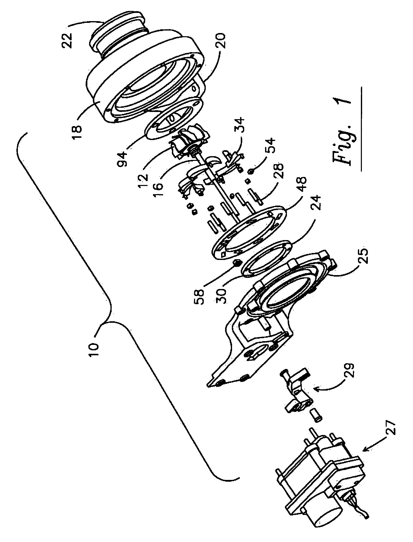
[0030] A turbocharger system as shown in FIG. 1 includes turbomachinery in the form of a turbocharger 10 generally comprising a turbine wheel 12 and a compressor impeller (not shown) mounted on opposite ends of a common shaft 16. The turbine wheel 12 may be disposed within a turbine housing 18 that includes an inlet 20 for receiving exhaust gas from an engine and an outlet 22 for discharging the exhaust gas. The turbine housing 18 guides the engine exhaust gas into communication with and expansion through the turbine wheel 12 for rotatably driving the turbine wheel 12. Such driving of the turbine wheel 12 simultaneously and rotatably drives the compressor impeller that may be carried within a compressor housing (not shown).
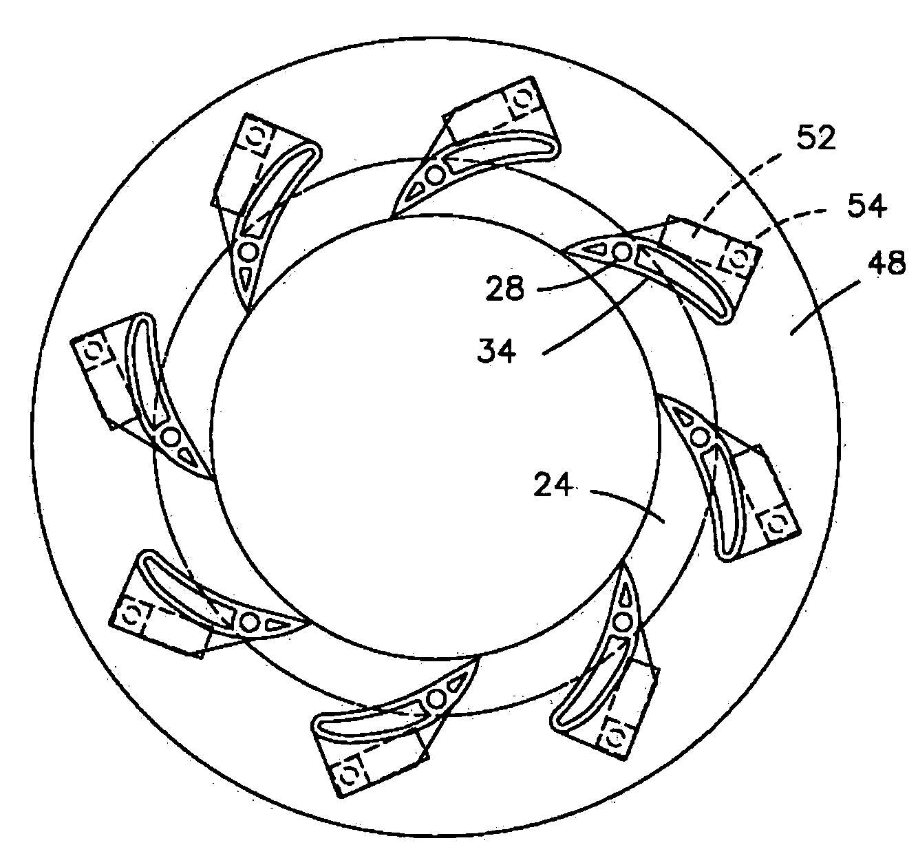
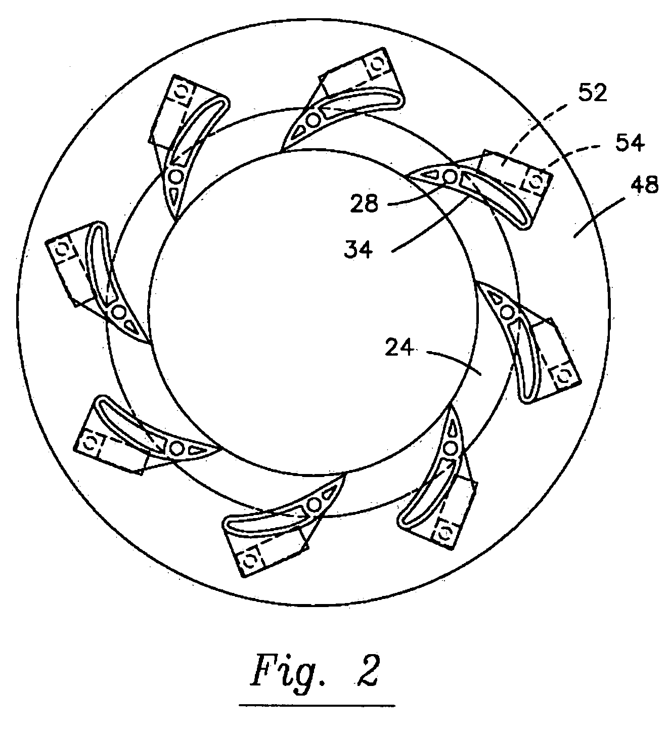
[0031]FIG. 1 shows a variable turbine geometry turbocharger with the turbine housing 18 having an exhaust gas inlet 20 and an outlet 22, a volute connected to the inlet 20, and a nozzle wall adjacent the volute (collectively referred to as the exhaust gas supply ...
PUM
 Abstract
Description
Claims
Application Information
 - R&D
- Intellectual Property
- Life Sciences
- Materials
- Tech Scout
- Unparalleled Data Quality
- Higher Quality Content
- 60% Fewer Hallucinations
Browse by: Latest US Patents, China's latest patents, Technical Efficacy Thesaurus, Application Domain, Technology Topic, Popular Technical Reports.
© 2025 PatSnap. All rights reserved.Legal|Privacy policy|Modern Slavery Act Transparency Statement|Sitemap|About US| Contact US: help@patsnap.com


