
Tunneler device

a technology of tunneling device and tunneling tube, which is applied in the field of tunneling device, can solve the problems of less effective dialysis treatment, less than optimal tip placement, and use of separate venous insertions

Inactive Publication Date: 2005-10-13
SHERWOOD SERVICES AG
View PDF20 Cites 28 Cited by
  • Summary
  • Abstract
  • Description
  • Claims
  • Application Information

AI Technical Summary

Benefits of technology

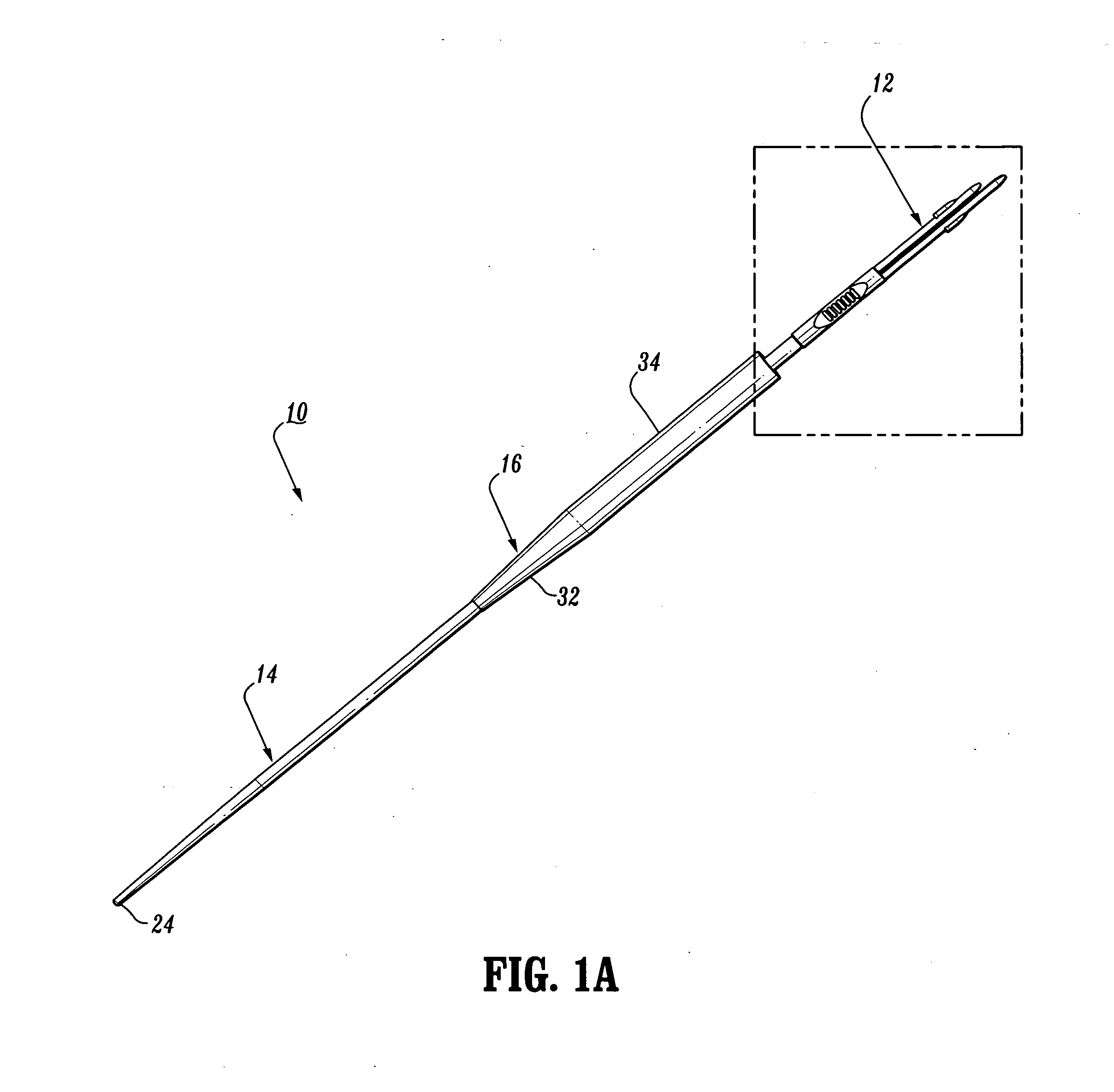
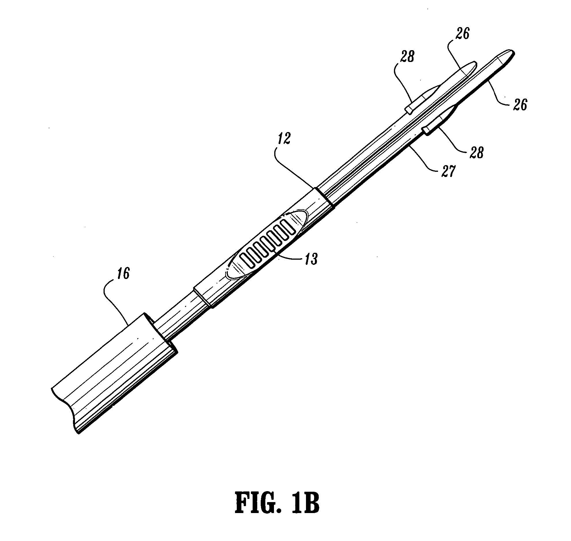
[0013] In one particular embodiment, a tunneling device is provided having a first end portion configured for insertion into a lumen of a catheter. The tunneler also includes a second end portion opposite the first end portion and a sheath member disposed between the first and second end portions. The sheath member has a plurality of inner diameters. The plurality of inner diameters increase in steps from one end of the sheath member to the other end thereof. Alternatively, the plurality of inner diameters taper from an end of the sheath member to the other end thereof. The stepped inner diameters of the sheath member engage an outer surface of the catheter to create an interference fit therebetween. The interference fit increases a catheter pull-off force.
[0014] In an alternate embodiment, the tunneler comprises a distal portion having at least one insert member configured for insertion into a lumen at a distal end of the catheter. The insert member has at least one projection for engaging an inner surface of the catheter lumen. The catheter is held onto the insert member by an interference fit therebetween created by an expansion of catheter material around the at least one projection. The tunneler also includes a proximal portion of metal construction and opposite the distal portion. This proximal portion has a blunt surface configured for subcutaneous tunneling. The sheath member is disposed between the distal and proximal portions. The sheath member has a portion with a tapered configuration and another portion with a rounded straight edge. The sheath member has an annular interior surface and a plurality of inner diameters. The plurality of inner diameters increase in steps from the tapered portion of the sheath member to the rounded straight edge portion thereof. The interior surface of the sheath member has stepped diameters that engage an outer surface of the catheter to create an interference fit therebetween. The interference fit between the interior surface of the sheath member and the outer surface of the catheter increases a force required to detach the catheter from the insert member.

Problems solved by technology

Non-optimal tip position may significantly lower flow values, resulting in less effective dialysis treatment.
The initial estimate and subsequent forward tunneling may result in less than optimal tip placement.
One problem associated with the use of catheters, for example, hemodialysis catheters, is the use of separate venous insertions, for example, two tunnels and two of each accessory instrument used for the procedure.
Therefore, there is increased surgical time required to place the catheters and two wound entry sites that doubles the risk of post-surgical infection.

Method used


Image

  • Tunneler device
  • Tunneler device
  • Tunneler device

Examples


Embodiment Construction

[0022] The various embodiments of the present invention may be used with medical catheters and related medical devices including the use and insertion of medical catheters for the administration of fluids (i.e., withdrawal, introduction and the like) with the body of a subject and more particularly, in terms of a catheter that facilitates placement with a body vessel. The tunneler may be configured to reduce trauma and prevent patient complications. It is envisioned that the tunneler of the present disclosure may be employed with a range of catheters, such as, for example, hemodialysis, peritoneal, infusion, PICC, CVC, port and catheter applications including surgical, diagnostic and related treatments of diseases and body ailments of a subject. It is further envisioned that the principles relating to the tunneler disclosed include use with various catheter related procedures, such as, for example, hemodialysis, cardiac, abdominal, urinary, intestinal and the like in chronic and acu...


PUM


Abstract

A tunneler is provided that includes a first end portion configured for insertion into a lumen of a catheter. The tunneler also includes a second end portion opposite the first end portion and a sheath member disposed between the first and second end portions. The sheath member includes a plurality of inner diameters that increase from one end to the other end thereof. Alternatively, the plurality of inner diameters taper from one end to the other end thereof. The inner diameter of the sheath member engages an outer surface of the catheter to create an interference fit therebetween. The interference fit increases a catheter pull-off force. A method of using the tunneler is also disclosed.

Description

RELATED APPLICATION INFORMATION [0001] This patent application claims priority from U.S. Provisional Application No. 60 / 561,010, filed with the United States Patent and Trademark Office on Apr. 9, 2004, the entire contents of which is incorporated herein by reference.BACKGROUND [0002] 1. Technical Field [0003] The present disclosure relates generally to tunneling devices for use with medical catheter apparatuses, and more particularly to a tunneling device for aiding medical catheter insertion. [0004] 2. Background of the Related Art [0005] Some known catheters are tubular, flexible medical devices for administration of fluids (i.e., withdrawal, introduction and the like) within veins, cavities, ducts and vessels of a body. [0006] These catheter devices may be employed for administration of fluids that include the simultaneous introduction and withdrawal of fluid for applications such as, surgery, treatment, diagnosis and the like. In one particular hemodialysis application, blood i...

Claims


Application Information

Patent Timeline
IPC IPC(8): A61B17/32A61B17/34A61M25/01
CPCA61B17/3415A61B2017/320044Y10T403/7077A61M25/0194A61B2017/320056
Inventor BRAGA, RICHARD
Owner SHERWOOD SERVICES AG
Learn More