

Free hand drill guide
a drill guide and hand-held technology, applied in bone drill guides, medical science, surgery, etc., can solve the problems of destroying the usefulness of the plate, affecting reducing the accuracy of the plate,
- Summary
- Abstract
- Description
- Claims
- Application Information
AI Technical Summary
Problems solved by technology
Method used
Image

Examples
Embodiment Construction
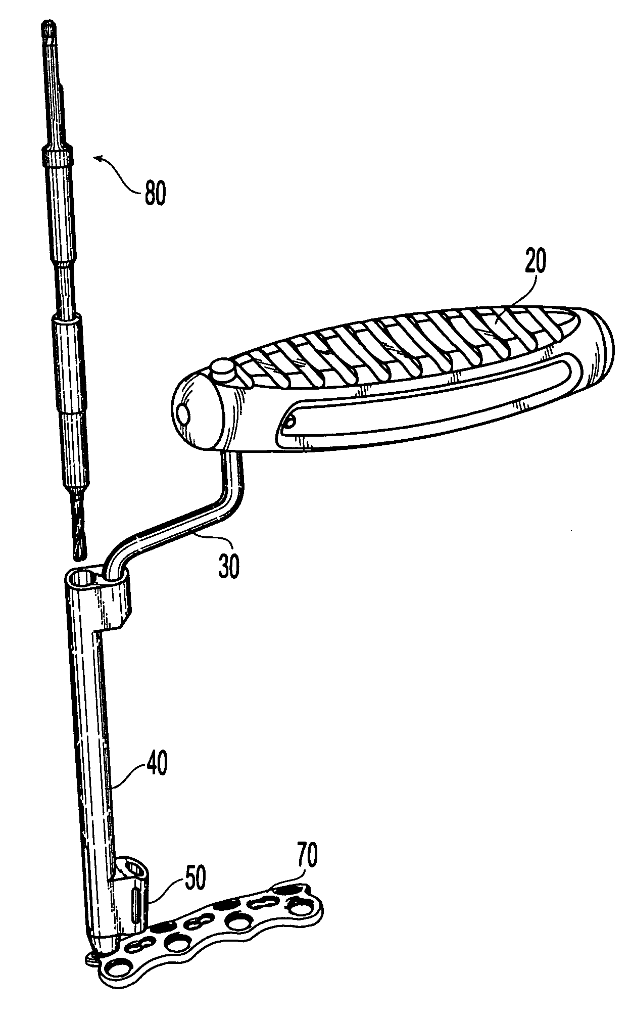
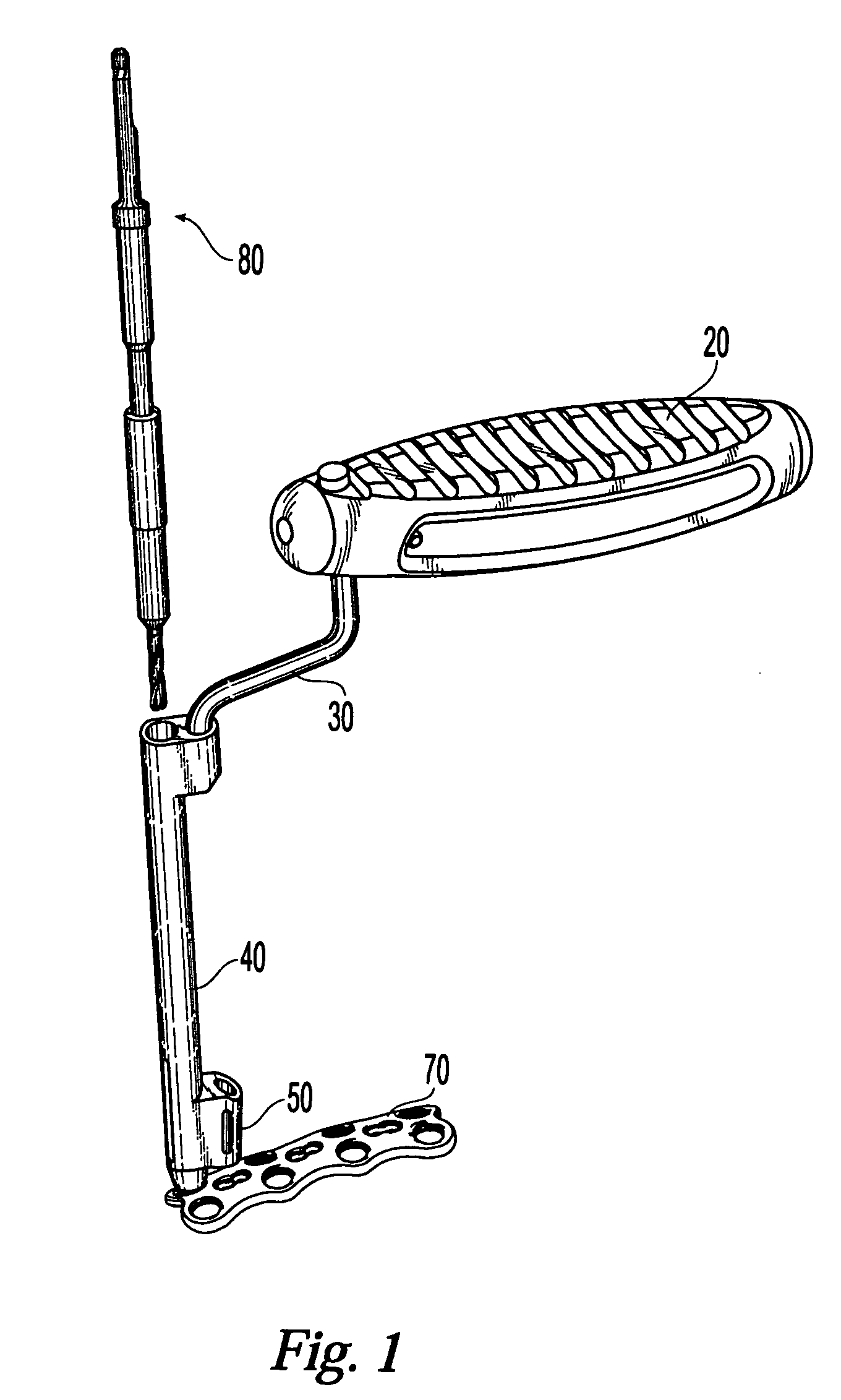
[0051] Referring to FIG. 1, there is shown an exemplary drill guide assembly 10, which is adapted for use with a spinal fixation device, such as for example, a spinal fixation plate 70. An exemplary spinal fixation plate may be that disclosed in co-pending United States non-provisional patent application Ser. No. 10 / 653,164, filed Sep. 3, 2003, entitled “Bone Plate with Captive Clips,” by Duong, et al., the entire disclosure of which is expressly incorporated by reference herein. It is noted, however, that while the drill guide assembly is disclosed in conjunction with a spinal fixation plate it is contemplated that the drill guide assembly may be used in conjunction with bone plates used on any portion of the body. Alternatively, in some instances the drill guide may be used without a bone plate. Drill guide assembly 10 generally includes a handle 20, an offset handle extension 30, a guide barrel 40, and a plate aligning mechanism 50. In general, to operate the drill guide assembly...
PUM
 Abstract
Description
Claims
Application Information