Connector for perforating gun tandem

a perforating gun and tandem technology, applied in the field of oil and gas production, can solve the problems of requiring manual attendants, premature detonation of explosives within the connector, and current connection devices that require manual attendants, and achieve the effect of facilitating automated engagemen

Active Publication Date: 2005-10-20
BAKER HUGHES INC
View PDF17 Cites 54 Cited by
  • Summary
  • Abstract
  • Description
  • Claims
  • Application Information

AI Technical Summary

Benefits of technology

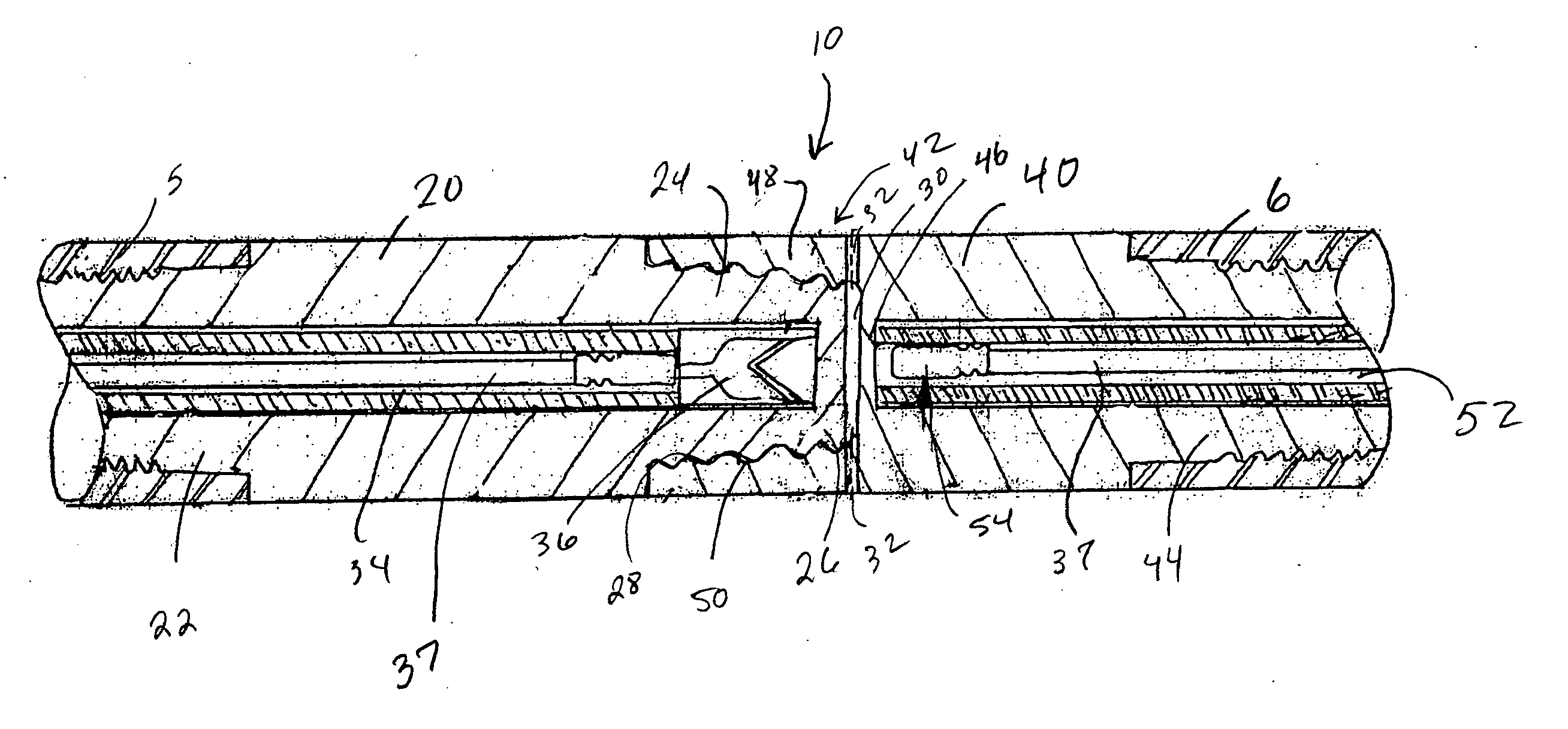
[0014] 3. The perforating gun connector of the present invention further includes a cavity formed by engaging the bottom end of the first section with the upper end of the second section. The cavity is disposed between the bottom end of the first section and the upper end of the second section. Also included with the present invention is at least one vent hole providing communication between the cavity and the outer surface of the upper end of the second section. The present invention further comprises a series of threads disposed on the outer surface of the bottom end of the first section. A hollowed out section is formed on the upper end of the second section. A series of threads is disposed on the hollowed out section. These threads are formed to cooperatively mate with the series of threads disposed on the outer surface of the bottom end of the first section. Alternatively, the threads considered on the hollowed out section and on the bottom end of the first section can be API threads. A further advantage of the present invention is realized by tapering the bottom end of the first section and the hollowed out section. Each section is correspondingly tapered for sealing engagement with the other section.
[0015] The perforating gun connector of the present invention further comprises an upper passage formed within the first section. The axis of the upper passage is substantially parallel with the axis of the first section. One end of the upper passage terminates at the upper bulkhead. The perforating gun connector of the present invention further comprises a lower passage formed within the second section. The axis of the lower passage is substantially parallel with the axis of the second section, and one end of said lower passage terminates at the lower bulkhead. The perforating gun connector of the present invention further comprises a first booster charge disposed in said upper passage proximate to said upper bulkhead and a second booster charge disposed in the lower passage proximate to the lower bulkhead.
[0016] The present invention considers a method of connecting at least two perforating guns with a perforating gun connector. The perforating gun connector comprises a first section having a top end, a bottom end, and a connector provided on its top end. The perforating gun connector further includes a second section having an upper end, a lower end, and a connector provided on the lower end. Wherein the bottom end of the first section is formed for cooperative engagement with the upper end of the second section. The method comprises connecting the top end of the first section to a first perforating gun, then connecting the bottom end of the second section to a second perforating gun. The method of the present invention can also include placing the top end that is connected to the first perforating gun into a pipe handling device and placing the bottom end that is connected to the second perforating gun in a pipe handling device, then operating the pipe handling device to engage said bottom end of the first section to the upper end of the second section, thereby securing the first perforating gun to the second perforating gun. The method of the present invention considers operating the pipe handling device in an automated fashion.
[0017] The method of the present invention further considers a perforating gun connection comprising a series of threads disposed on the outer surface of the bottom end of the first section, a hollowed out section formed on the upper end of the second section, and a series of threads disposed on the hollowed out section. The series of threads formed on the upper end of the second section are formed to cooperatively mate with the series of threads disposed on the outer surface of said bottom end of said first section. The method of the present invention further comprises rotating the first section about its axis with respect to the second section while contacting the bottom end of the first section with the hollowed out section on the second section thereby causing the series of threads disposed on the bottom end of the first section to engage the threads formed on the hollowed out section of the second section. The method of the present invention comprises the bottom end of the first section being tapered and the hollowed out section being correspondingly tapered to facilitate automated engagement with the tapered bottom end.BRIEF DESCRIPTION OF THE SEVERAL VIEWS OF THE DRAWING
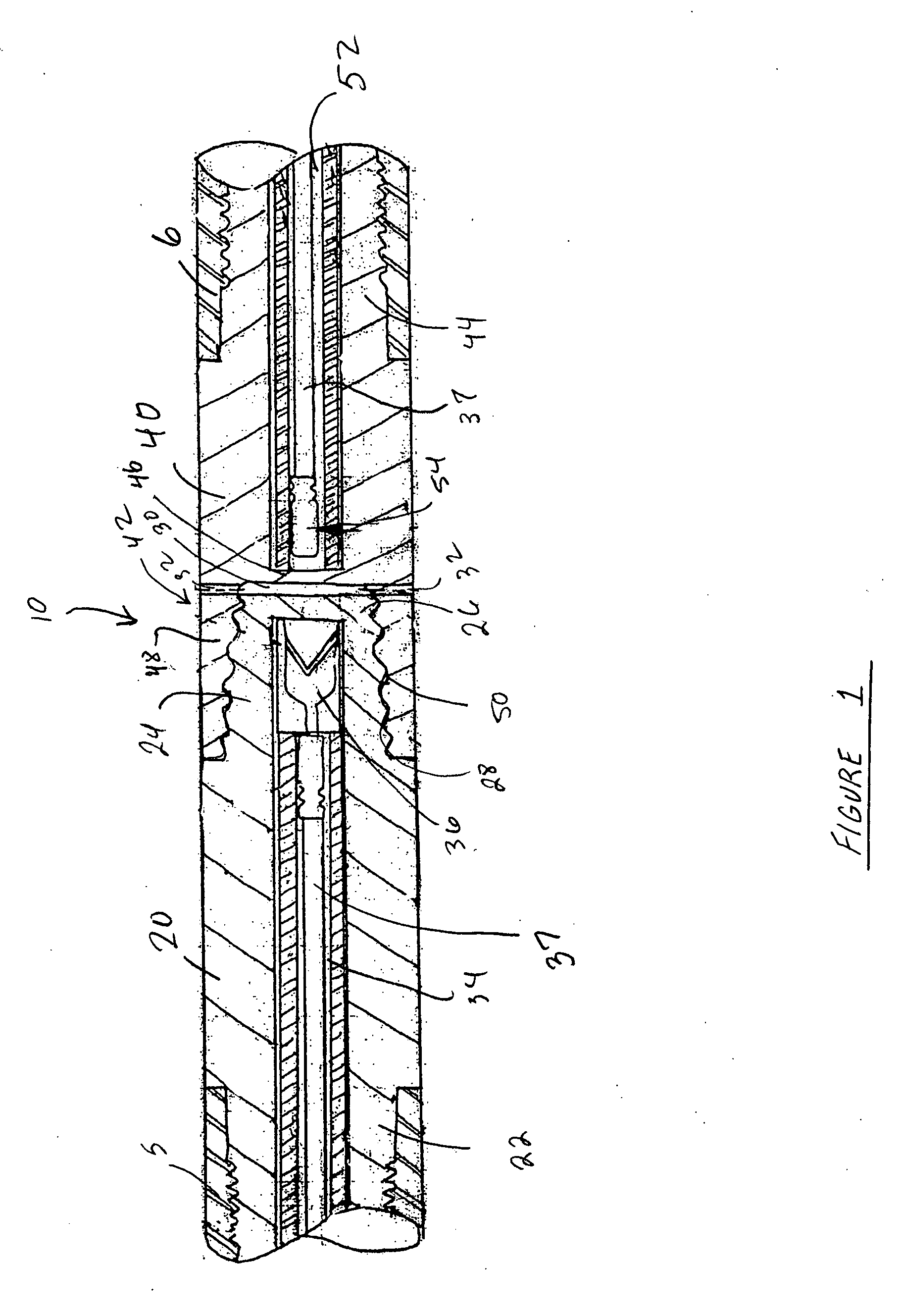
[0018]FIG. 1 depicts a cross sectional view of one embodiment of the present invention.

Problems solved by technology

One of the problems with this technique is that current connection devices require a manual attendant to be present at the site where the perforating gun connector sections are being joined.
Further, in situations where the first and second booster charges within the connectors are exposed, attendants are needed to prevent the sections from impacting one another in a manner that could prematurely detonate the explosives within the connectors.
This currently known operation of connecting perforating guns however is hazardous to attendant personnel who actually perform the connecting.
Further, the presence of the high explosives within the connectors and the perforating guns require extra care.
While these handling considerations could be greatly reduced if the connection procedure were automated, all other known connection means on the perforating gun connection sections are incapable of being reliably connected by mechanical means, such as with a pipe-handling device.
For example, prior art perforating gun connectors that are coupled with a pipe-handling device are prone to become cross-threaded.
Further the controllability of mechanical coupling devices make it difficult to accurately insert a hoisted section into a secured section, which can not only lead to the cross threading problem, but can also result in possible damage to the explosives within the connectors.

Method used


Image

  • Connector for perforating gun tandem
  • Connector for perforating gun tandem

Examples


Embodiment Construction

[0019] With reference to the drawings herein, a cross sectional view of one embodiment of a perforating gun connector 10 of the present invention is illustrated in FIG. 1. Here, the perforating gun connector 10 comprises a first section 20 and a second section 40 connected together. As shown in FIG. 1, the top end 22 of the first section 20 is threaded to provide a manner of attaching the first section 20 to a first perforating gun 5, where the first perforating gun 5 has corresponding threads formed on its outer radial surface. Many alternatives exist however for attaching the first section 20 to the first perforating gun 5, such as dogs, latch keys, collets, threaded fasteners such as bolts, screws, or lugs, and any other known or later developed attachment device. Likewise, the second section 40 is threaded on its lower end 44 as shown in FIG. 1 for attachment to a second perforating gun 6. Furthermore, the attachment alternatives that exist for the first section 20, exist for th...


PUM

PropertyMeasurementUnit
explosive chargeaaaaaaaaaa
chargeaaaaaaaaaa
velocityaaaaaaaaaa

Abstract

A perforating gun connector comprising a first and second section connected together on one end. The two sections of the perforating gun connector that couple together are correspondingly tapered so that one end of one connector is tapered and fits into the corresponding tapered hollowed section of one end of the other section. The present invention also provides for the inclusion of shaped charges and booster charges within. Adjacent the charges are sealing bulkheads.

Description

RELATED APPLICATIONS [0001] This application claims priority from co-pending U.S. Provisional Application Ser. No. 60 / 486,101, filed Jul. 10, 2003, the full disclosure of which is hereby incorporated by reference herein.BACKGROUND OF THE INVENTION [0002] 1. Field of the Invention [0003] The invention relates generally to the field of oil and gas production. More specifically, the present invention relates to an apparatus that connects perforating guns. Yet more specifically, the present invention relates to a perforating gun connector utilizing corresponding tapered ends to facilitate connections thereof. Yet even more specifically, the present invention relates to an automated method of connecting perforating guns with a perforating gun connector. [0004] 2. Description of Related Art [0005] Perforating guns are used for the purpose, among others, of making hydraulic communication passages, called perforations, in wellbores drilled through earth formations so that predetermined zone...

Claims


Application Information

Patent Timeline
Patent Type & Authority Applications(United States)
IPC IPC(8): C06C5/00E21B17/042E21B43/117
CPCE21B17/042F42D1/043E21B43/117E21B43/116
Inventor MYERS, WILLIAM D. JR.VAN SICKLE, EDGAR W.VARGERVIK, KRISTIAN
Owner BAKER HUGHES INC
Why Eureka
Try Eureka