

Safety fence at upper part of cab
a safety fence and upper part technology, applied in the direction of elevators, transportation and packaging, building lifts, etc., can solve the problems of difficult to ensure a safe operating space for service personnel, significant limitation of ceiling plates, and the area of upper surface, so as to enhance the safety of service personnel and improve the coupling rigidity between various holding members
- Summary
- Abstract
- Description
- Claims
- Application Information
AI Technical Summary
Benefits of technology
Problems solved by technology
Method used
Image

Examples
first embodiment
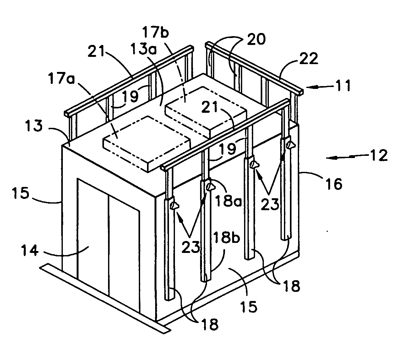
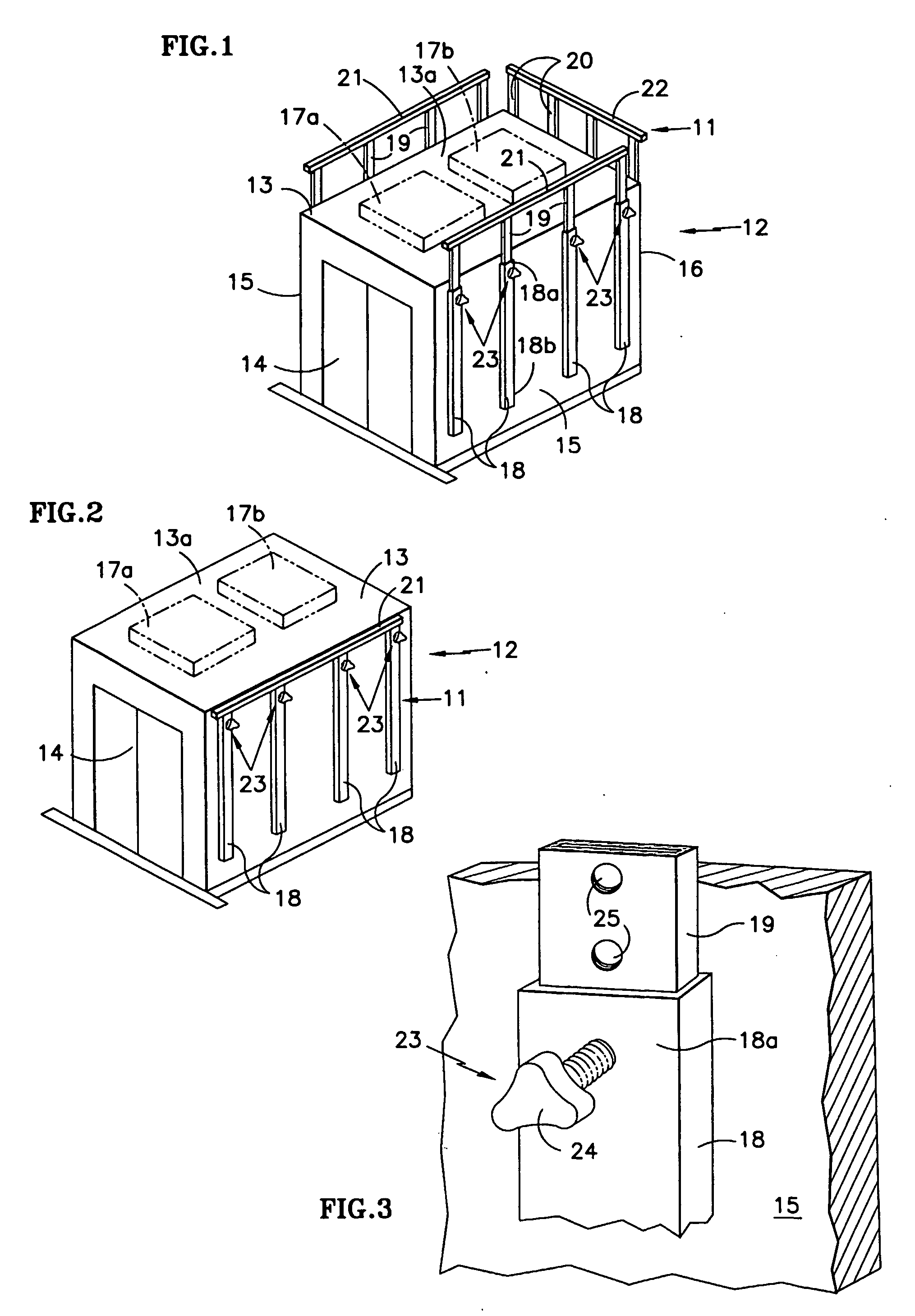
[0031]FIGS. 1 and 2 illustrate safety fence (11) in the present invention. First, car (12), on which safety fence (11) is placed, will be briefly explained. It has the same boxlike form as the conventional car, and it is mainly composed of a bottom plate (not shown in the figure) that forms the bottom wall, ceiling plate (13) that forms the ceiling wall, slide door (14) that is set on the front side and can be opened in the left / right direction, two side plates (15), (15) that form the two side walls, and back plate (16) that forms the rear end wall. Equipment, such as control equipment (17a), (17b), etc., is arranged on upper surface (13a) of said ceiling plate (13).
[0032] Said safety fence (11) is formed of the following parts: multiple holding members (18) arranged and fixed along the vertical direction on two side plates (15), (15) and back plate (16) of car (12); columns (19), (19) on the side of two side plates (15), (15) and columns (20) on the side of back plate (16), held i...
second embodiment
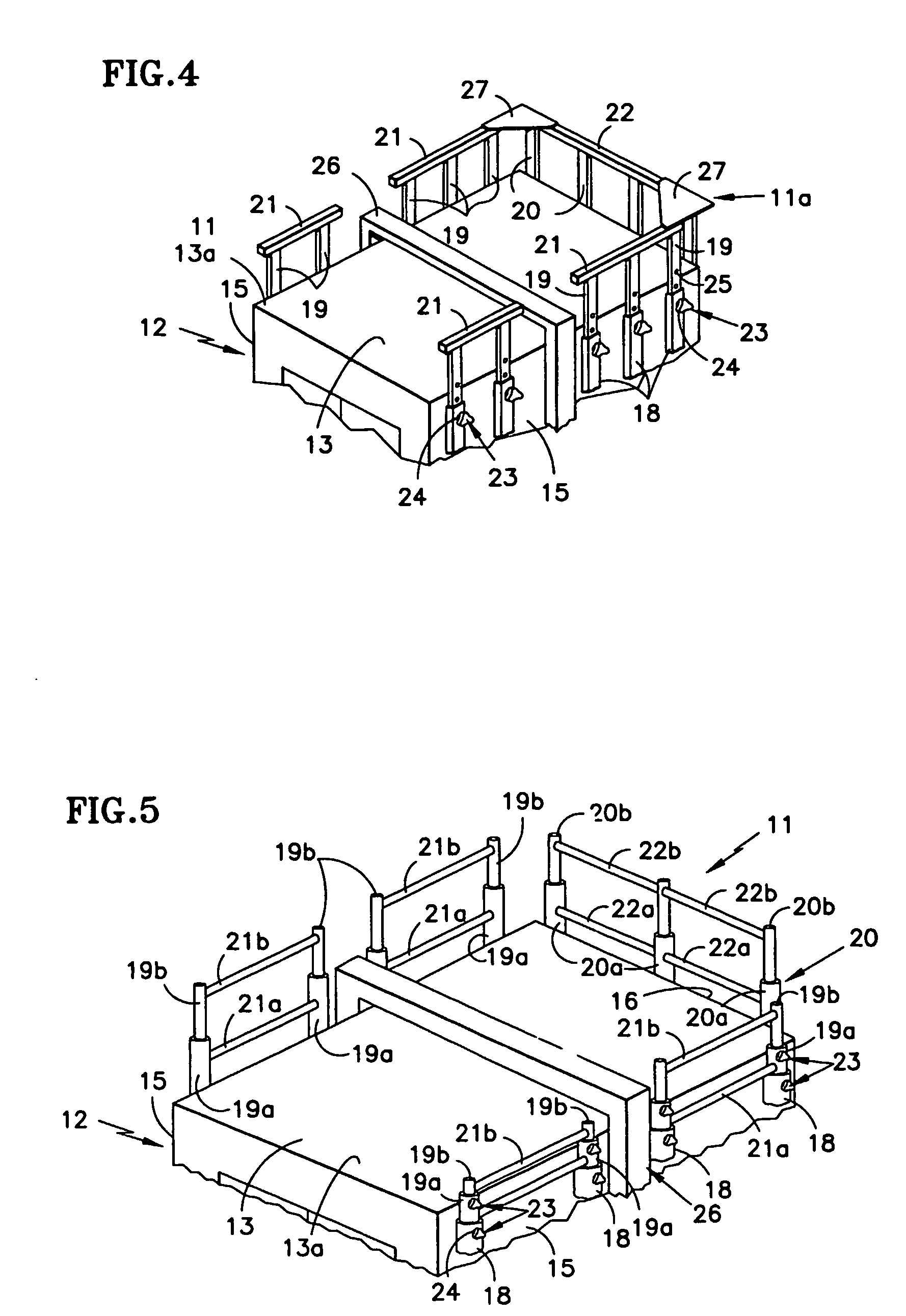
[0045]FIG. 4 is a diagram illustrating the present invention. In this embodiment, car (12) is longer than it is wide, and a car frame member (26) is attached at nearly the center of said car (12) in the outer peripheral front / rear direction and running from the outer side of two side plates (15), (15) to above ceiling plate (13).
[0046] On the other hand, the basic constitution of safety fence (11), that is, holding members (18), columns (19), (19), (20) and handrails (21), (21), (22) is the same as that of said first embodiment. However, it is formed as a front portion and a rear portion with said car frame (26) at the center, and the number of columns (19), (19) on each of the two sides is increased. Handrails (21), (21) attached to the upper end portions are separated into front and rear sections. Also, left / right handrails (21), (21) of separated safety fence (11a) on the rear side is connected to handrail (22) on the back side by means of connecting members (27), (27).
[0047] Sa...
third embodiment
[0052]FIG. 5 is a diagram illustrating the present invention. In this case, columns (19), (19), (20) of safety fence (11) are formed in a 2-step constitution.
[0053] That is, holding members (18) fixed by welding or the like on two side plates (15), (15) and back plate (16) are formed in an approximately hollow cylindrical form. Inside said holding members (18), columns (19a), (19b), (20a), (20b) in a telescoping structure are accommodated to be freely extendible vertically. Said holding members (18) are fixed with four on each of two side plates (15), (15), and with three holding members on back plate (16). Also, in addition to said hollow cylindrical form, holding members (18) may also have a hollow, square shape.
[0054] Said first columns (19a), (20a) on the outer side are in a hollow, cylindrical shape with a smaller diameter. They are set such that they can slide freely vertically inside holding members (18), and, at the same time, cylindrical first handrails (21a), (22a) are us...
PUM
 Abstract
Description
Claims
Application Information