
Skimmer

a technology of skimmer and spouting chamber, which is applied in the direction of settling tank feed/discharge, water cleaning, separation process, etc., can solve the problems of troublesome removal of fats, oils and grease floating in pans and pots where meats and pastas are cooked,

Inactive Publication Date: 2005-10-20
COOPER MICHELE
View PDF59 Cites 23 Cited by
  • Summary
  • Abstract
  • Description
  • Claims
  • Application Information

AI Technical Summary

Benefits of technology

[0007] The present invention relates to a skimmer device and a method for skimming a liquid, foam, fat or other solid or liquid material or anything else that a user wants to remove or separate from a remaining liquid or solid that is left in the container. The present invention relates to a skimmer device and a method for skimming a layer of fat, oil, or other similar layer that is floating on top of another liquid. It is an object of the present invention for the other liquid to be water or soup or other similar substance. It is an object of the present invention for the device to be placed in a pot or other container. It is an object of the present invention for the device to be used to skim a layer of foam, such as that formed at the top of a pot of cooked pasta, from the surface of a liquid. It is an object of the present invention for the invention to comprise a flange around the outside to prevent the device from dropping to the bottom of the pot.
[0011] The stopper is the rotatable, slidable, or otherwise positionable piece of material that opens the holes in the strainer to permit the ingress of the liquid, fat, foam or other similar material to be removed, or alternatively close the holes in the strainer, allowing the skimmed liquid to be retained in the reservoir without draining out through the holes in the strainer. It is an object of the present invention for the stopper to be positioned above or below the strainer. It is an object of the present invention for the stopper to sit above the strainer within the reservoir. The holes in the stopper are the same size and in the same relative position as the holes in the strainer, when the stopper is aligned in the open position. When the stopper is moved or rotated into the closed position, the solid portions of the stopper completely block the holes in the strainer. The surface of the stopper forms a tight seal against surface of the strainer in the closed position, to prevent leakage of liquid from the reservoir when the skimmer is withdrawn from the pot. It is an object of the present invention for the stopper to be rotated or slid into position via the action of the stopper control rod. It is an object of the present invention for the stopper to comprise a thin, round, plate made of either a hard material, such as metal or plastic, or of a gasket-like material, with an array of holes matching the holes in the strainer.
[0015] It is an object of the present invention for the component pieces of the skimmer to be disassembled to permit easy cleaning.
[0017] The present invention can be used at the time of cooking, before adding solid materials such as bones or vegetables to a liquid material that one may want to remove after cooking. In this instance, the user would first place the skimmer into a pot, either with or without the liquid in the open position. The user could then add the solid materials such as bones or vegetables or meats (as in preparing a gravy) and commence with the cooking of the liquid. Once cooked, the skimmer can be removed in the open position allowing for the removal of the solids from the liquid.

Problems solved by technology

The removal of fats, oils and grease floating in pans and pots where meats and pastas are cooked is troublesome.

Method used


Image

  • Skimmer
  • Skimmer
  • Skimmer

Examples


Embodiment Construction

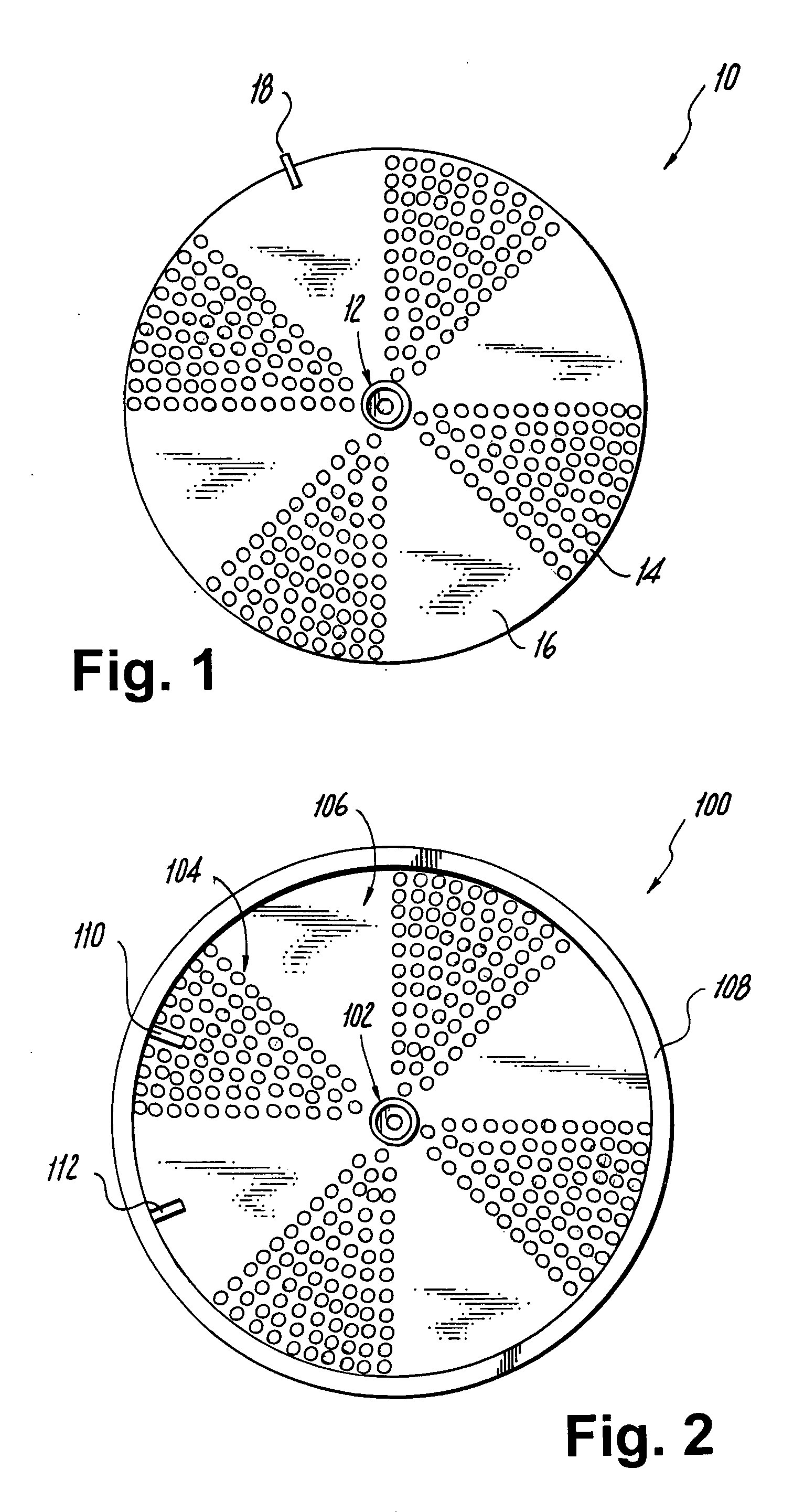
[0023]FIG. 1 shows a skimming device 10 being of a round or circular shape having a center pivot pin 12, stopper holes 14 and solid area 16. The device further comprises a mechanical rotation stop 18. The device 10 can be divided into a different number of segments which have various hole sizes or shapes.

[0024]FIG. 2 shows a skimming device 100 having a center pivot hole 102, strainer holes 104 and solid area 106. FIG. 2 further comprises a reservoir wall 108. The mechanical stops 110 and 112 limit the rotation of the device 100.

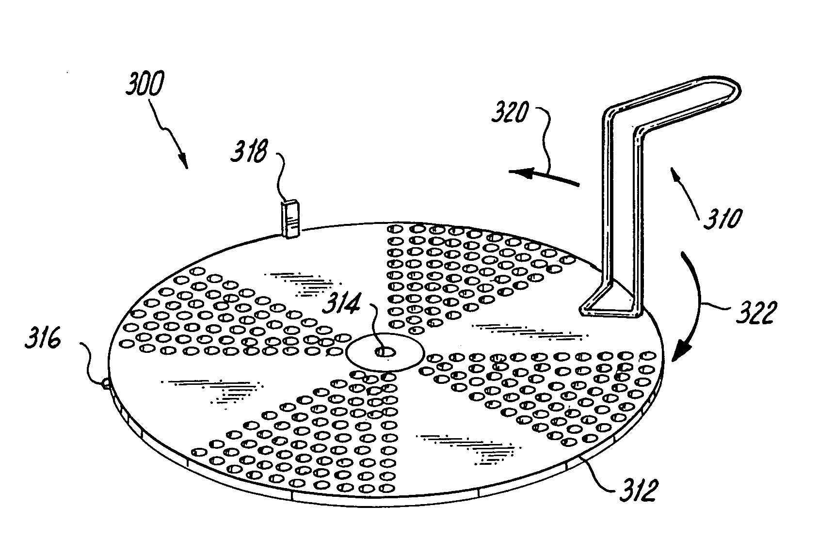
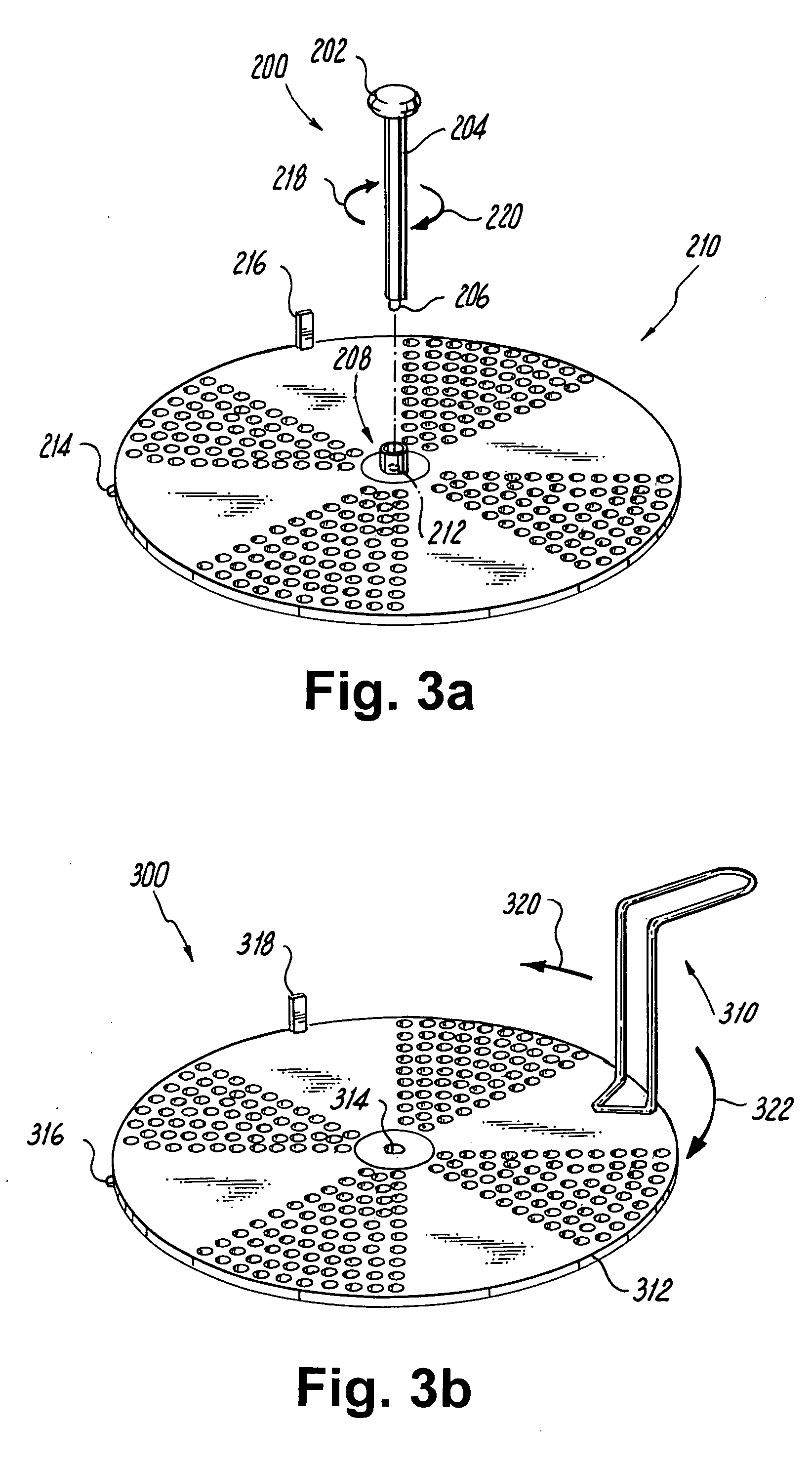
[0025]FIG. 3a shows a stopper control rod 200 comprising a handle 202, rod 204 and a key 206 which is inserted into the flange seat 208. The flange seat 208 is for a fixed or removable stopper control rod. Skimming device 210 has a pivot 212 which is located under the center of the flange. Skimming device 210 also has a round stopper 214 and a mechanical rotational stop pin 216. The device is opened by turning the device following arrow 220 and closed foll...


PUM

PropertyMeasurementUnit
sizeaaaaaaaaaa
diameteraaaaaaaaaa
transparentaaaaaaaaaa

Abstract

A skimmer device and a method for skimming a liquid, foam, fat or other solid or liquid material or anything else that a user wants to remove or separate from a remaining liquid or solid that is left in a container.

Description

RELATED APPLICATIONS [0001] The present application claims priority to provisional patent application Ser. No. 60 / 563,507, filed Apr. 18, 2004.FIELD OF THE INVENTION [0002] The present invention relates to a skimmer device and a method for skimming a liquid, foam, fat or other solid or liquid material or anything else that a user wants to remove or separate from a remaining liquid or solid that is left in the container. BACKGROUND OF THE INVENTION [0003] U.S. Pat. No. 5,077,900 relates to a fat skimmer in the form of a ladle having a deep vessel bowl with a rim at which there are ports for the transfer of surrounding fatty liquid into the vessel, determined by manipulation controlled by a locator associated with the rim. [0004] U.S. Pat. Nos. D252,068, D493,070 and D357,389 relate to fat skimmer devices. to a fat skimmer for separating an unwanted fat liquid from a wanted liquid. The device consists of a transparent cone shaped jug for storing the unwanted fat liquid and the wanted ...

Claims


Application Information

Patent Timeline
Patent Type & Authority Applications(United States)
IPC IPC(8): A47J36/20A47J43/28B01D19/02B01D21/24C02F1/40
CPCA47J36/20A47J43/285C02F1/40B01D21/2433B01D19/02
Inventor COOPER, MICHELE
Owner COOPER MICHELE
Learn More