Flexible wall and ceiling storage and retention system

a storage and storage system technology, applied in the field of flexible storage devices, can solve the problems of occupying much needed floor space, items may fall forward or become disorganized, items may become dislodged and fall, etc., and achieve the effect of efficient utilization of the space between

Inactive Publication Date: 2005-10-20
CASE LOGIC
View PDF21 Cites 26 Cited by
  • Summary
  • Abstract
  • Description
  • Claims
  • Application Information

AI Technical Summary

Benefits of technology

[0008] Thus, it is one aspect of the present invention to provide a storage device that is adapted for interconnection to adjacent wall studs, thus efficiently utilizing the space therebetween. Alternatively, a storage device is provided that is adapted for interconnection to the horizontal beams of rafters utilizing the space therebetween. One embodiment of the present invention is employed in unfinished basements or garages, wherein the unit may be installed flush with respect to adjacent wall studs or rafter beams. Thus, it is contemplated that the invention efficiently utilizes the space between wall studs or ceiling rafters that is often filled with insulation, conduits, wires, or otherwise unused.

Problems solved by technology

One drawback of common storage devices is that they often take up much needed floor space.
However, these items may fall forward or become disorganized because they are not sufficiently constrained.
One drawback to this storage method is that the items may become dislodged and fall, possibly injuring bystanders or damaging property thereunder.
Other types of flexible storage mechanisms have previously been used for holding hand tools, and which are adapted for removable interconnection to pegboard or other materials with nails or screws, but do not provide any means for operably interconnecting two or more flexible panels in series in either a vertical or horizontal orientation.

Method used


Image

  • Flexible wall and ceiling storage and retention system
  • Flexible wall and ceiling storage and retention system
  • Flexible wall and ceiling storage and retention system

Examples


Embodiment Construction

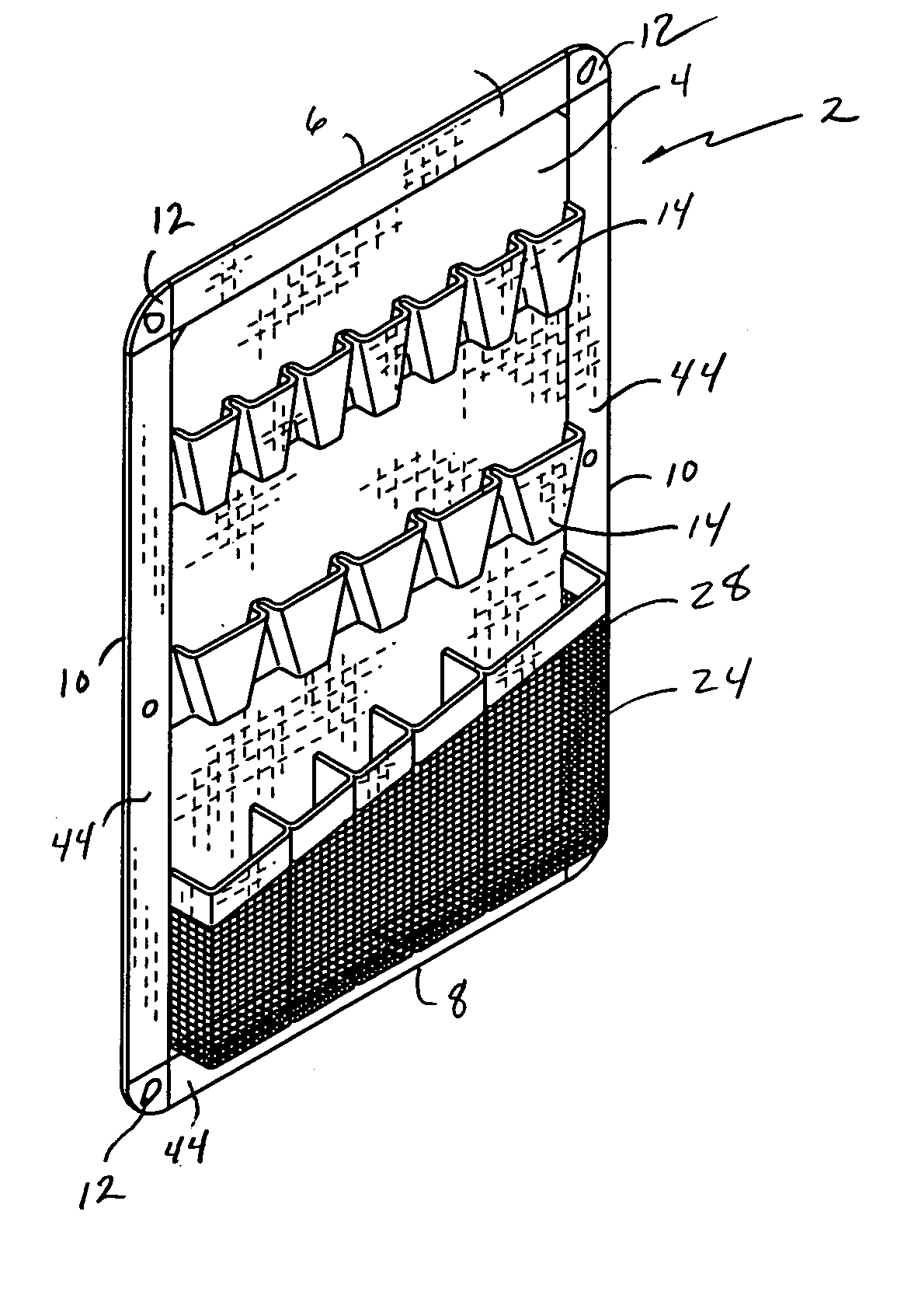
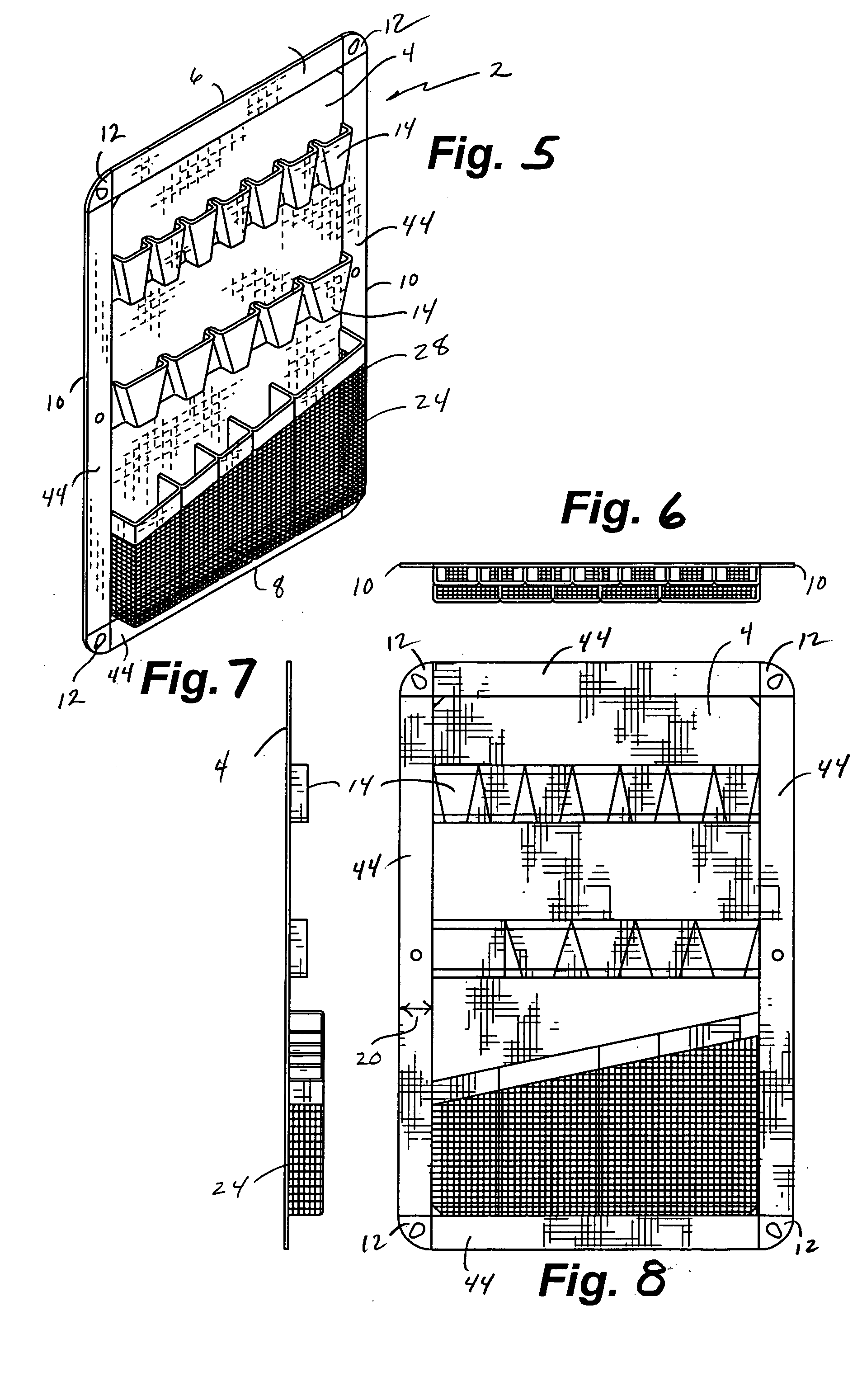
[0050] Referring now to the drawings, FIGS. 1-4 depict various views of one embodiment of the present invention. More specifically, a flexible storage device 2 is provided which generally comprises a panel 4 with an upper edge 6, a lower edge 8 and lateral edges 10 extending therebetween. In each corner of this particular embodiment, corner attachment hardware 12 is provided to allow the flexible storage device 2 to be interconnected to a wall stud or other vertical support member. The corner attachment hardware 12 in one embodiment is comprised of a metallic plate with an aperture 50 adapted to fit over a screw, nail, hook, or other type of hardware.

[0051] As further shown in FIGS. 1-4, this embodiment of the present invention further includes a mesh material 24 to allow viewing of the contents positioned within the storage bin 28, and may further include a belt 36 and buckle 38 to provide additional support. As appreciated by one skilled in the art, the length of the storage devi...


PUM


Abstract

The present invention relates generally to storage devices that are adapted for interconnection to a vertical or horizontal surface and to secure and a plurality of items. More specifically, some embodiments of the - present invention are adapted for interconnection between two adjacent wall studs to utilize the area therebetween, and which utilize a novel interconnection system wherein two or more storage devices can be operatively interconnected by utilizing common attachment hardware. In addition, some embodiments of the present invention are adapted to fold and are preferably provided with handles to facilitate transportation of the storage container.

Description

[0001] This application claims the benefit of U.S. Provisional Patent Application Ser. Nos. 60 / 540,608, 60 / 625,635, 60 / 592,030 and 60 / 625,520, filed Jan. 29, 2004, Nov. 4, 2004, Jul. 28, 2004 and Nov. 4, 2004, respectively, all of which are incorporated by reference in their entirety herein. In addition, this application is a Continuation-In-Part of U.S. Design patent application Ser. Nos. 29 / 210,911, 29 / 210,912, 29 / 214,597, 29 / 214,573, 29 / 215,536, 29 / 217,498, 29 / 217,480, and 29 / 217,507 filed Aug. 5, 2004, Aug. 5, 2004, Oct. 5, 2004, Oct. 5, 2004, Oct. 19, 2004, Nov. 17, 2004, Nov. 17, 2004, and Nov. 17, 2004, respectively, all of which are incorporated by reference in their entirety herein. Finally, this application is a Continuation-In-Part of U.S. Design patent applications filed on Jan. 10, 2005 that have yet to receive a serial number, but are identified by attorney file numbers 2417-614 and 2417-618, express mail receipt nos. EV539130858 and EV539130929, respectively, all of w...

Claims


Application Information

Patent Timeline
Patent Type & Authority Applications(United States)
IPC IPC(8): A47B43/00A47B81/00A47F5/08B25H3/04
CPCA47B43/00A47B81/00A47G29/08B25H3/04A63C2203/44A63C17/0006
Inventor MUNDY, CACHEHASSETT, ERIC S.PHILLIPS, MARK E.
Owner CASE LOGIC
Why Eureka
Try Eureka