Automatic formation flight control system

a flight control and automatic technology, applied in the field of transportation, can solve the problems of difficult, if not impossible, to achieve the effect of precise, precise and precise positive control of aircraft flying

Inactive Publication Date: 2005-10-20
CORCORAN JAMES J III
View PDF17 Cites 109 Cited by
  • Summary
  • Abstract
  • Description
  • Claims
  • Application Information

AI Technical Summary

Benefits of technology

[0007] One advantage of the invention is to provide discrete, precise, positive control of aircraft flying in formation flight.
[0008] Another advantage of the invention is to provide discrete navigational, positional and performance control to aircraft in formation flight.
[0009] A further advantage of the invention is to provide discrete ‘look-ahead’ computation for each aircraft in formation flight. Air turbulence, winds aloft acting on the formation can be calculated quickly to permit corrections before the condition affects the formation or individual aircraft. This information can be shared quickly with each aircraft in the formation.
[0010] Yet another advantage of this invention is that it provides discrete formation displays for cockpit reference for any number of aircraft in formation flight.
[0011] A significant additional advantage is to provide a technical basis through discrete aircraft identification to guide aircraft through an air traffic control system by broadcasting flight directions electronically to the cockpit and having the aircraft react to those instructions. This would also allow another aircraft or ground control to take control of the aircraft in the event of a highjacking or other form of incapacitation of the flight crew.

Problems solved by technology

Weather, turbulence and speed have contributed to accidents even under the best of circumstances.
Due to equipment restrictions and the need for visual contact or radar surveillance, positive control was difficult if not impossible.

Method used


Image

  • Automatic formation flight control system
  • Automatic formation flight control system
  • Automatic formation flight control system

Examples


Embodiment Construction

[0020] A detailed description of the preferred embodiment is provided herein. It is to be understood, however, that the present invention may be embodied in various forms. Therefore, specific details disclosed herein are not to be interpreted as limiting, but rather as a basis for the claims and as a representative basis for teaching one skilled in the art how to employ the present invention in an appropriately detailed system, structure or manner.

DETAILED DESCRIPTION OF THE INVENTION

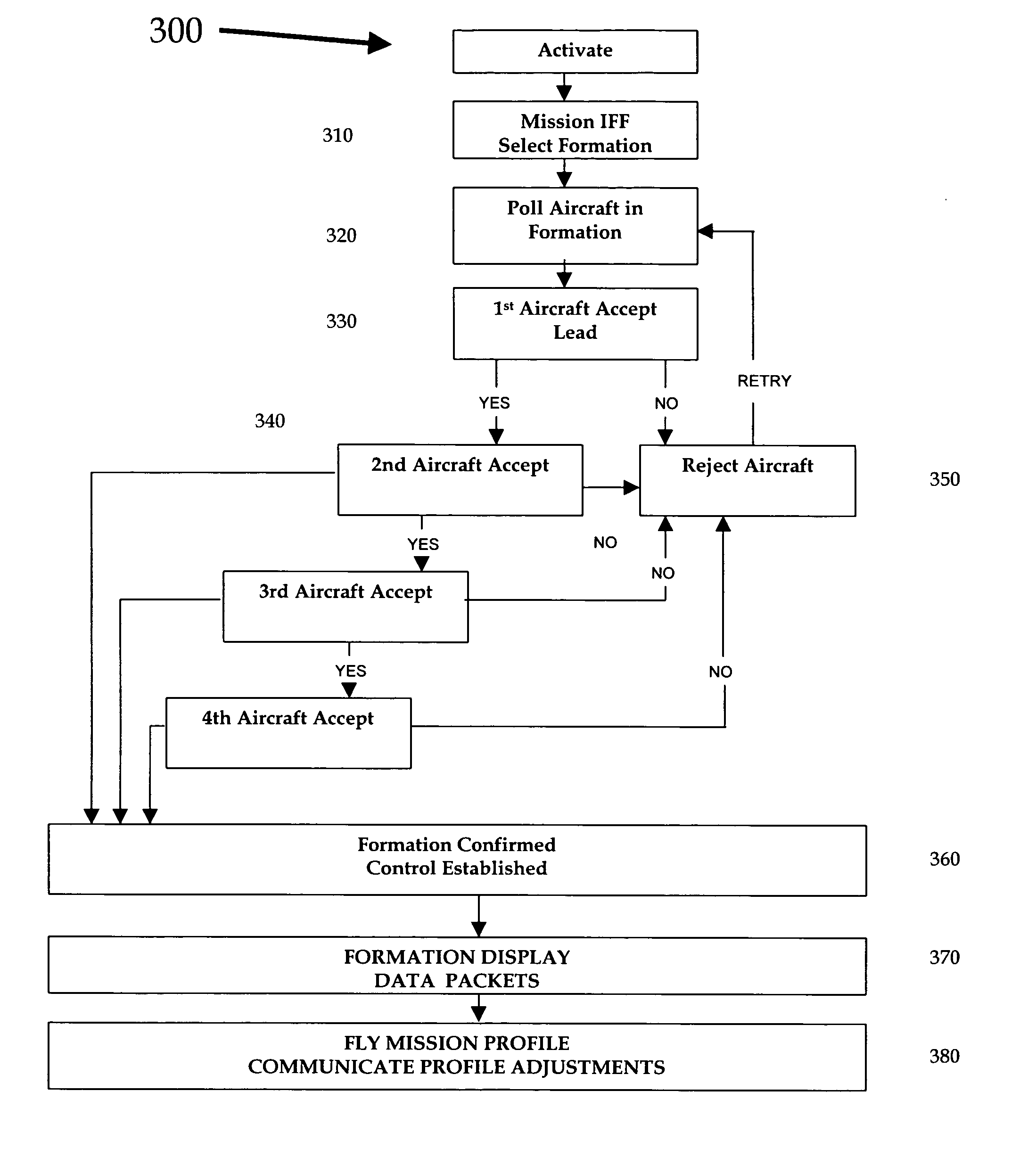
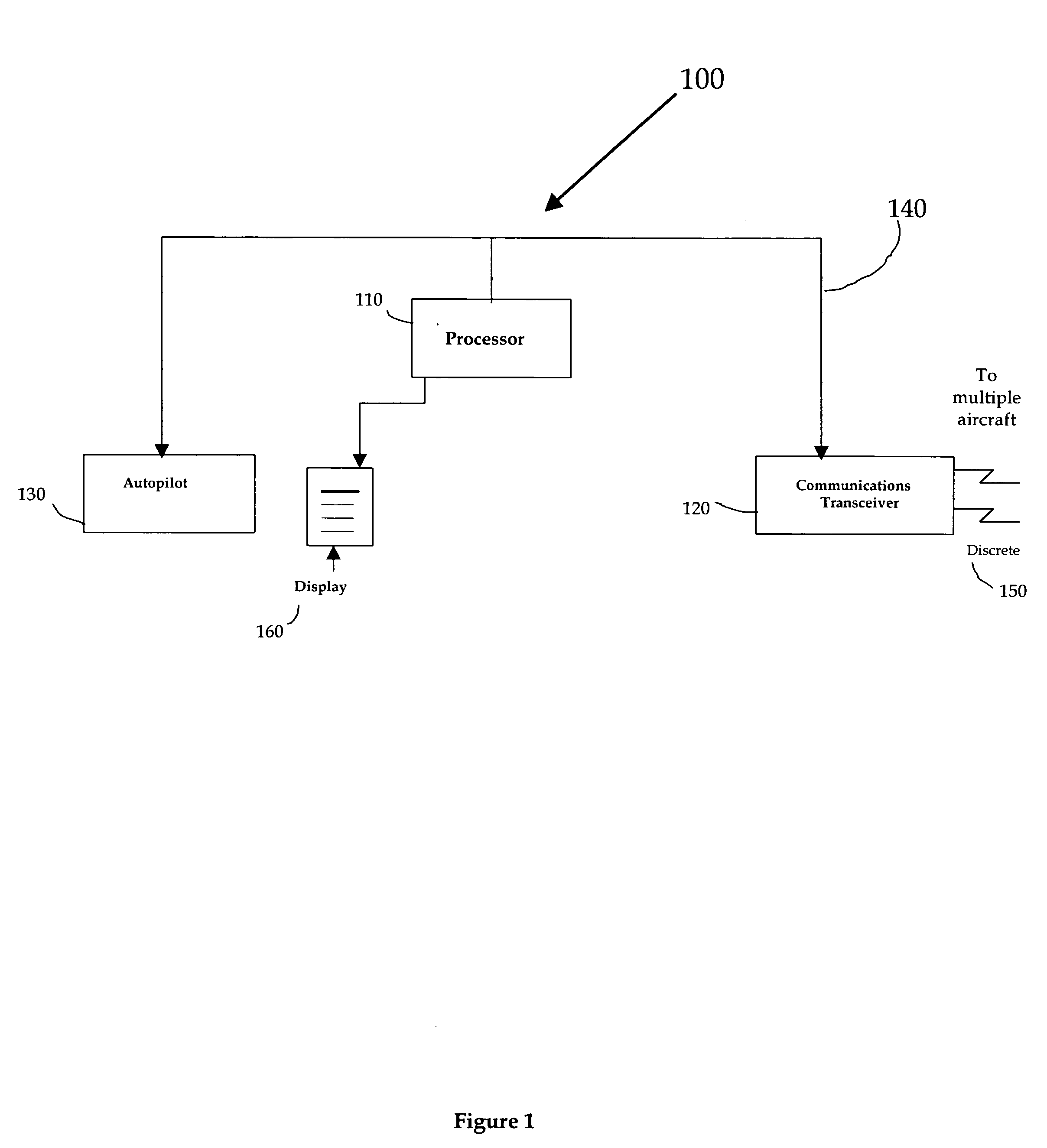
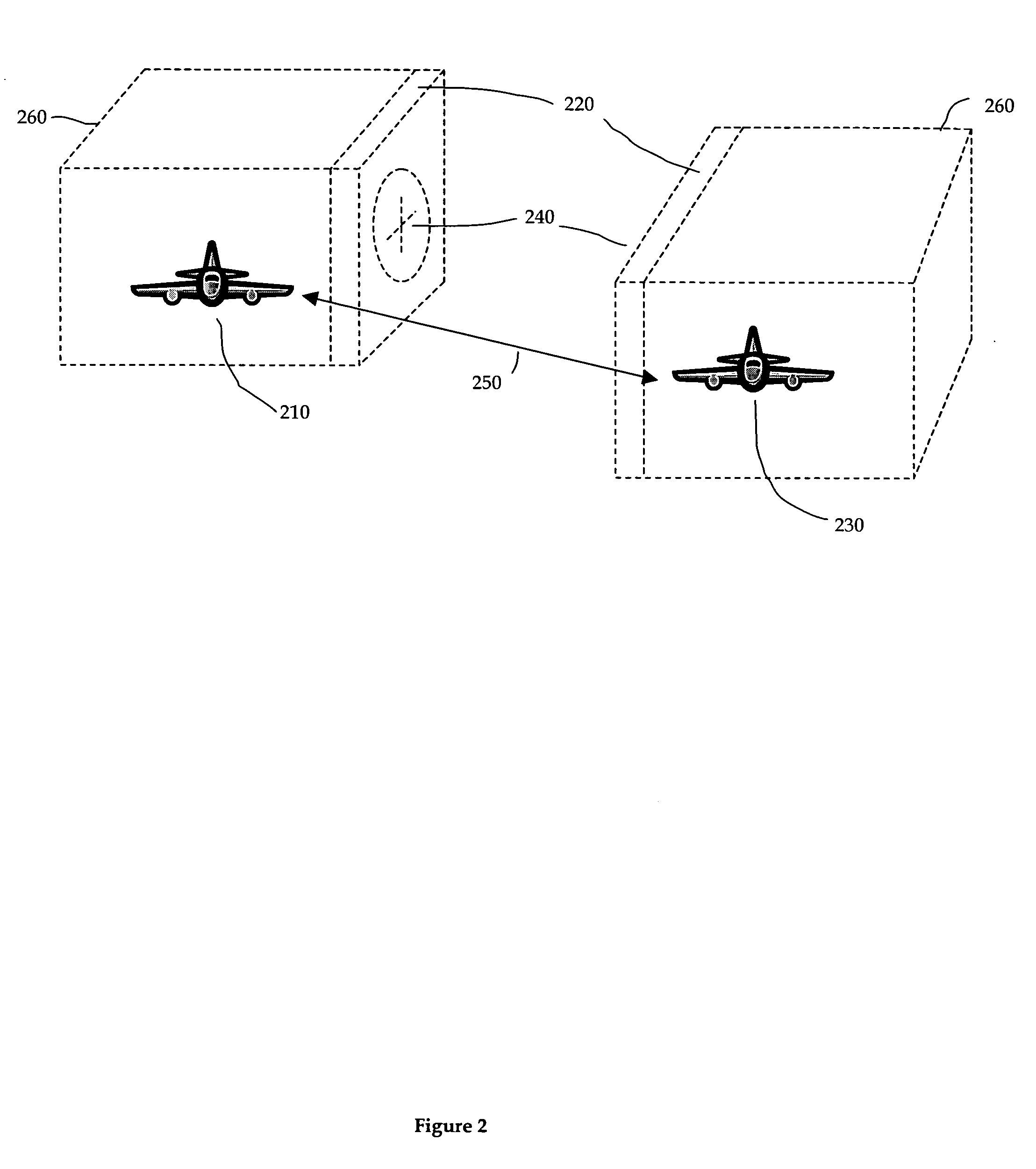
[0021] The present invention provides a system, a method and a process for automatic formation flight control for use in either commercial or military flight applications of fixed wing aircraft, helicopters, space vehicles or the like. The system is used to avoid mid-air collisions during formation flight and provide guidance to aircraft requiring close maneuvering in flight regimes, orbital flight and maneuvering as part of some of the exemplary embodiments. It also may be utilized to provide interve...


PUM


Abstract

An integrated system for automatic formation flight control of multiple vehicles such as aircraft, helicopters, or space platforms. The system is used to control multiple aircraft in a pre-determined flight formation and provide positive identification, control and discrete communications between any number of aircraft in order to prevent mid-air collisions between aircraft in formation flight. The system includes a processor located on the aircraft to enable communications, position computations and control messaging between any number of aircraft in formation flight, a communications transceiver located on the aircraft that provides discrete communication links to any number of aircraft or aircraft in formation flight, an autopilot, an autothrottle and a display. On aircraft, the system will display the current formation and aircraft relative positions under control by the system. The system may also be used to circumvent control of a hijacked aircraft through control system intervention provided through this invention.

Description

CROSS REFERENCE TO RELATED APPLICATIONS [0001] This application is related to pending application Ser. No. 10 / 784660, filed Feb. 21, 2004, herein incorporated by reference.BACKGROUND OF THE INVENTION [0002] This invention relates generally to the field of transportation and more specifically to a system for automatic formation control of aircraft. Particular utility exists in the automatic formation of flights of aircraft of any type and specifically not restricted to or not limited to commercial or military aircraft, helicopters, unmanned aircraft, missiles, or space platforms. It may also be used to enable automated air traffic control and to provide control of hijacked aircraft from the ground or another aircraft with similar equipment. [0003] Formation flight has always been the cornerstone of both precision flight and mission execution. In tight formation flight, a single radar image is displayed on a radar screen. Presenting one radar image, size or surprise is a key to milita...

Claims


Application Information

Patent Timeline
Patent Type & Authority Applications(United States)
IPC IPC(8): B64C3/00B64C9/00B64C13/18B64C13/20G05D1/10
CPCG05D1/104B64C13/20B64C13/18B64D45/0031B64U2201/102
Inventor CORCORAN, JAMES J. III
Owner CORCORAN JAMES J III
Why Eureka
Try Eureka