Method of braking an airplane having a plurality of braked wheels

a technology of brakes and airplanes, applied in the direction of braking systems, automatic braking sequences, aircraft braking arrangements, etc., can solve the problems of considerable limit on the performance of brakes, difficulty in implementation, and limitation that must be lowered even further, so as to reduce the maximum braking force

Inactive Publication Date: 2005-10-20
MESSIER BUGATTI INC
View PDF21 Cites 46 Cited by
  • Summary
  • Abstract
  • Description
  • Claims
  • Application Information

AI Technical Summary

Benefits of technology

[0009] An object of the invention is to provide a method of braking an airplane having a plurality of wheels that can be braked in controlled manner, and making it possible reliably to reduce the maximum braking force while avoiding the drawbacks of the prior art.

Problems solved by technology

This initial overshoot is most troublesome insofar as it leads to a transient braking force of large intensity which needs to be taken into account when dimensioning the undercarriage and the structure of the airplane.
In practice, that turns out to be very difficult to implement since it is very difficult to measure the braking force being developed by a given braked wheel.
This limitation must therefore be lowered even further since the instantaneous performance of a brake is difficult to predict, which leads to taking safety margins that put a considerable limit on the performance of the brake.
However the highly non-linear nature of the response of the brake makes such control extremely uncertain.
Nevertheless, operating in that manner requires logic that is complex.
Thus, although braking is applied simultaneously on all of the wheels, if the anti-wheel-lock system is in operation, it can happen that the transient force on some of the wheels on the undercarriage acts at different moments in time compared with the transient force from other wheels of the undercarriage, thereby diminishing the overall transient braking force to which the undercarriage is subjected.
Nevertheless, this reduction is transient and presents a highly random nature, which means that it cannot be taken into account when dimensioning the undercarriage.

Method used


Image

  • Method of braking an airplane having a plurality of braked wheels
  • Method of braking an airplane having a plurality of braked wheels
  • Method of braking an airplane having a plurality of braked wheels

Examples


Embodiment Construction

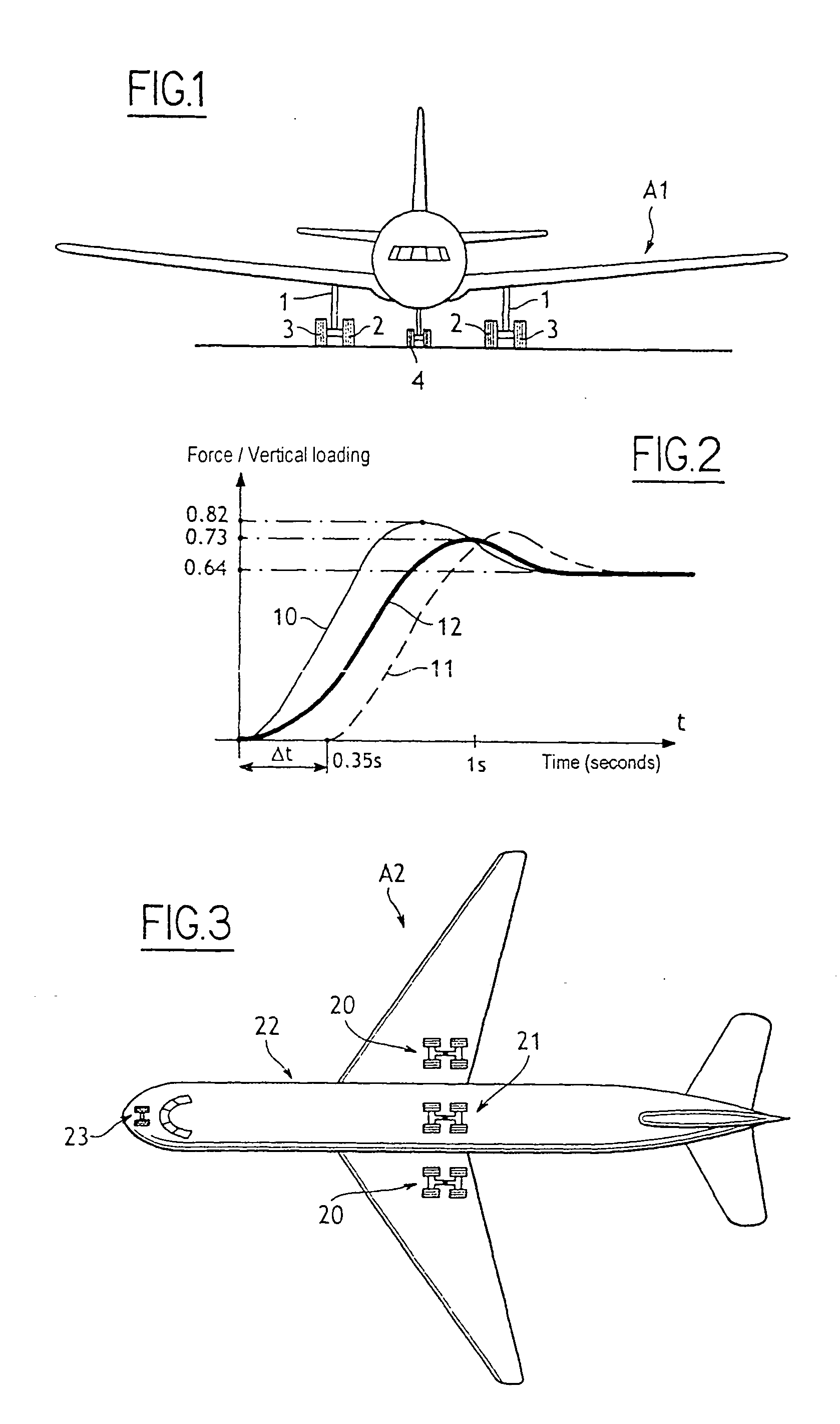
[0025] With reference to FIG. 1, the method of the invention is applied to an airplane A1 (e.g. of the Airbus A320 or Boeing 737 type) having two main undercarriages 1 each carrying an inner braked wheel 2 and an outer braked wheel 3 in a diabolo configuration.

[0026] The airplane is also fitted with an auxiliary undercarriage 4 fitted with wheels that are not braked.

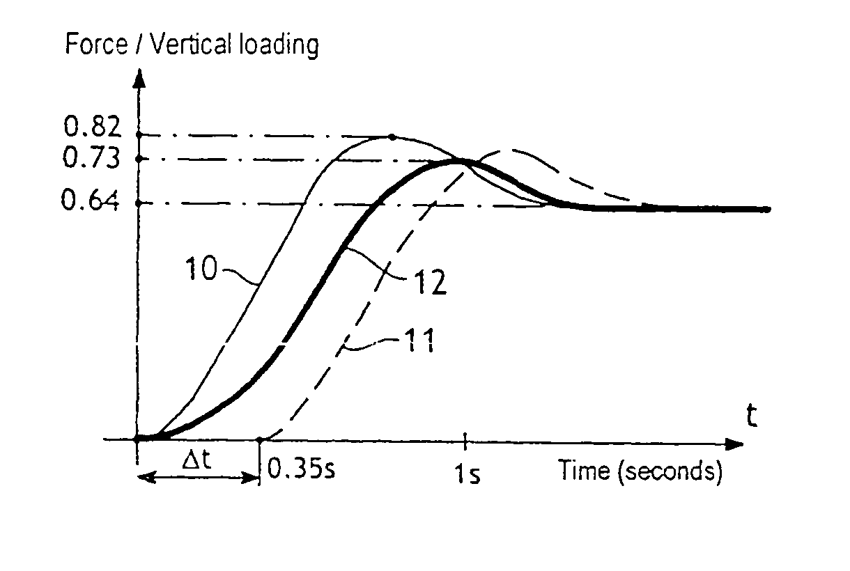
[0027] During braking on landing, the method of the invention consists in applying the brakes in a first group of braked wheels, specifically the group constituted by the inner wheel 2 of the two main undercarriages 1, and then after a time offset, in applying the brakes to a second group of braked wheels, specifically the group constituted by the outer wheel 3 of the two main undercarriages 1.

[0028] The braking as performed in this way remains symmetrical, and therefore does not deflect the path followed by the airplane.

[0029] It should be observed that runways are generally cambered, sloping down from the axis of t...


PUM


Abstract

The invention relates to a method of braking an airplane having a plurality of wheels capable of being braked in controlled manner, the method comprising the step of applying braking to a first group of wheels of the airplane, and then after a time offset, applying braking to a second group of wheels of the airplane.

Description

[0001] The invention relates to a method of braking an airplane having a plurality of braked wheels. BACKGROUND OF THE INVENTION [0002] The ratio of the braking force developed by a braked wheel and the vertical load acting on the wheel is representative of the friction acting between the tire of the wheel and the runway. It is well known that the value of this ratio depends on various parameters such as the state of the runway, the degree of wear of the tire, or indeed the speed of the airplane. In addition, the value of this ratio varies during braking: prior to reaching a stabilized value, the ratio presents an initial overshoot of value that is greater than said stabilized value. [0003] This initial overshoot is most troublesome insofar as it leads to a transient braking force of large intensity which needs to be taken into account when dimensioning the undercarriage and the structure of the airplane. This transient braking force can in particular be the determining factor when ...

Claims


Application Information

Patent Timeline
Patent Type & Authority Applications(United States)
IPC IPC(8): B60T8/17B64C25/42
CPCB64C25/426B60T8/1703
Inventor FRANK, DAVID
Owner MESSIER BUGATTI INC
Why Eureka
Try Eureka