Stepping motor

a technology of stepping motors and stepping plates, applied in the field of stepping motors, can solve the problems of increasing manufacturing costs, inability to rotate, and difficulty in integral structure of parts from the perspective of parts manufacturing, and achieve the effect of high output and high resolution

Inactive Publication Date: 2005-10-20
CANON KK
View PDF24 Cites 77 Cited by
  • Summary
  • Abstract
  • Description
  • Claims
  • Application Information

AI Technical Summary

Benefits of technology

[0013] It is a first object of the present invention to provide a stepping motor which is inex

Problems solved by technology

H10-229670 has a problem in that magnetic flux lines generated by energization of a first coil adversely affects a second coil, a second outer magnetic pole portion, and a second inner magnetic pole portion via the output shaft formed of a soft magnetic material, and magnetic flux lines generated by energization of a second coil adversely affects a first coil, a first outer magnetic pole portion, and a first inner magnetic pole portion via the output shaft formed of a soft magnetic material, resulting in unstable rotation.
H10-229670 both require a predetermined clearance between the inner periphery of the magnet and the inner magnetic pole portion opposed thereto, and management of the clearance during manufacture causes an increase in manu

Method used


Image

  • Stepping motor
  • Stepping motor
  • Stepping motor

Examples


embodiment 1

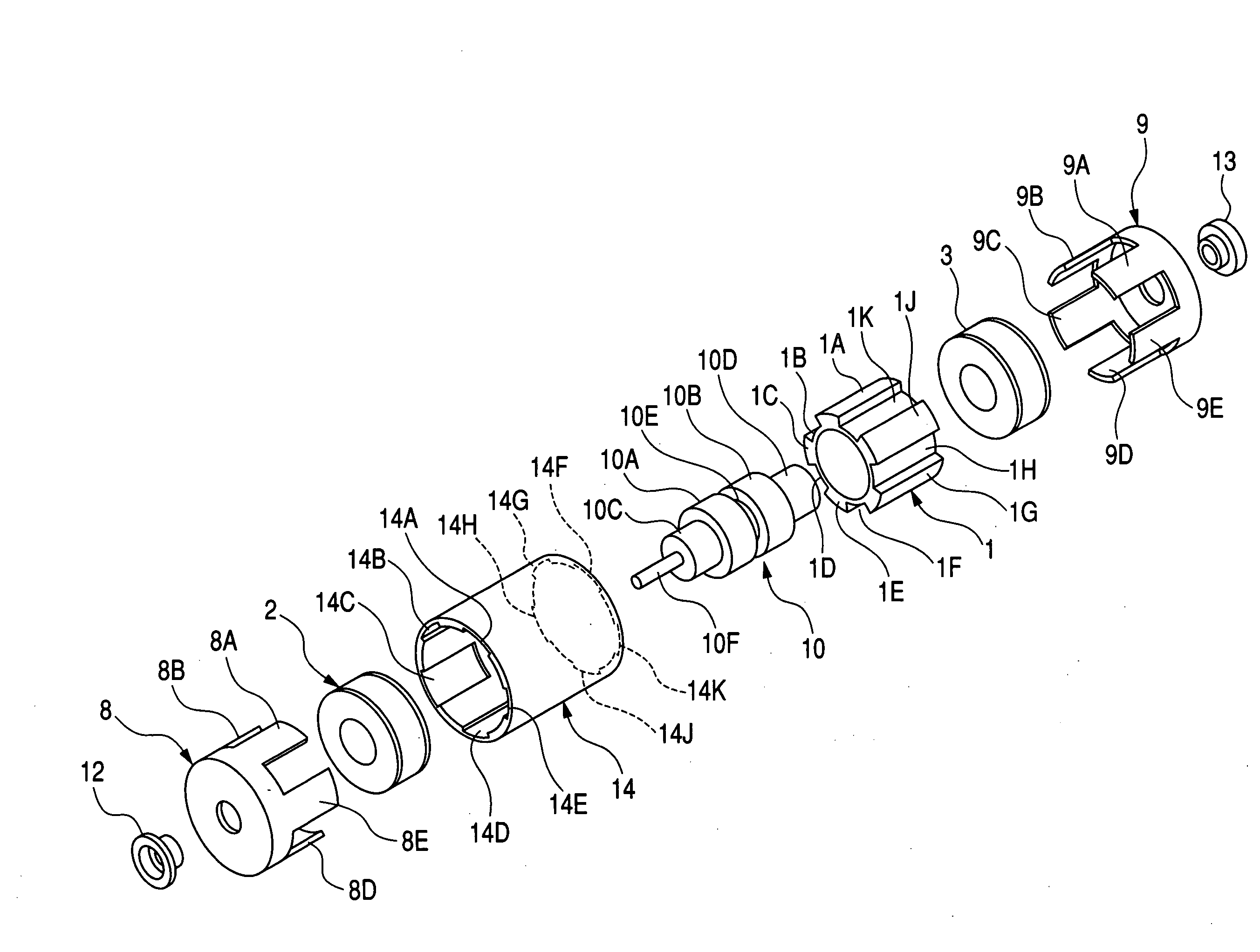
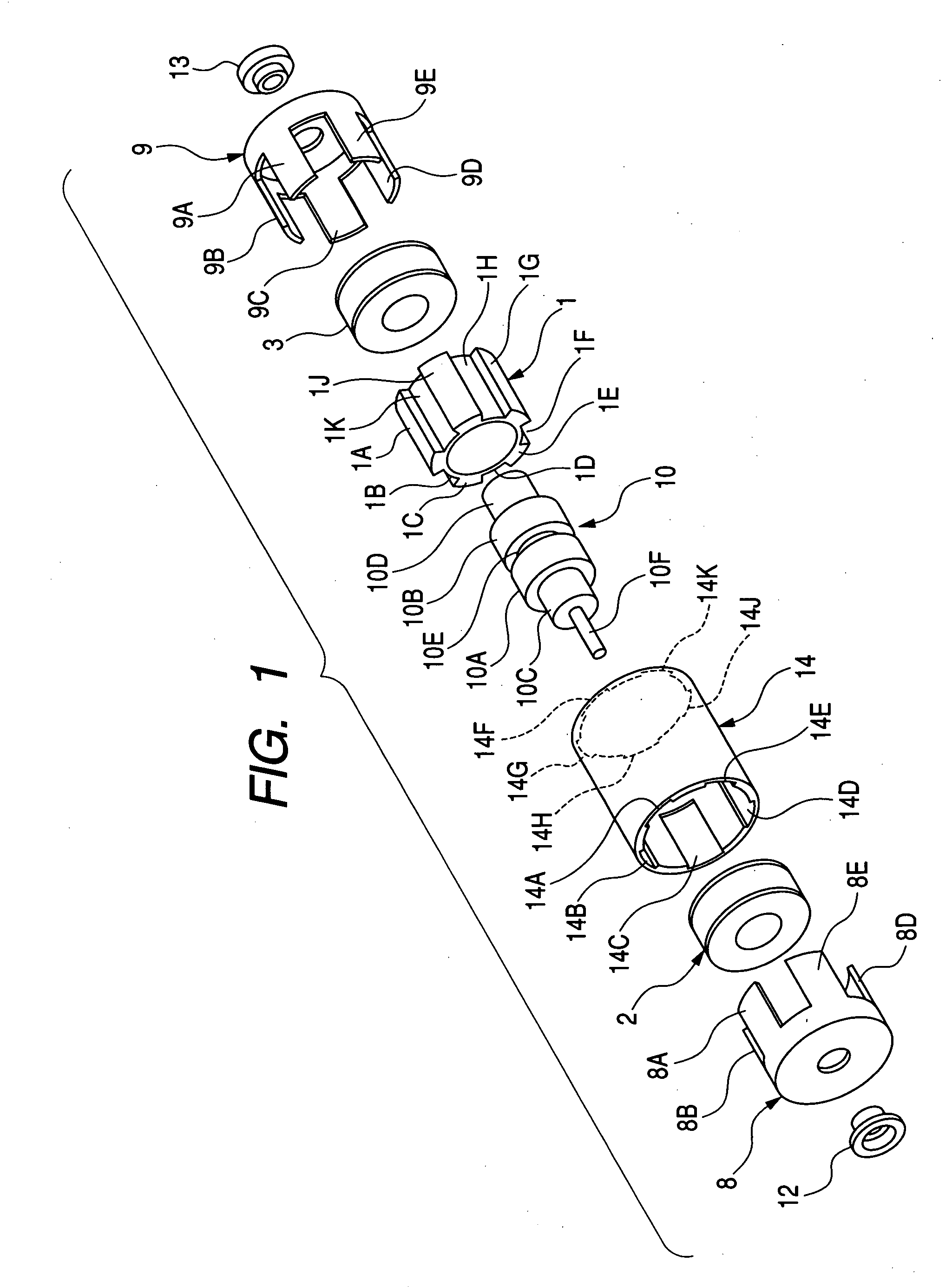
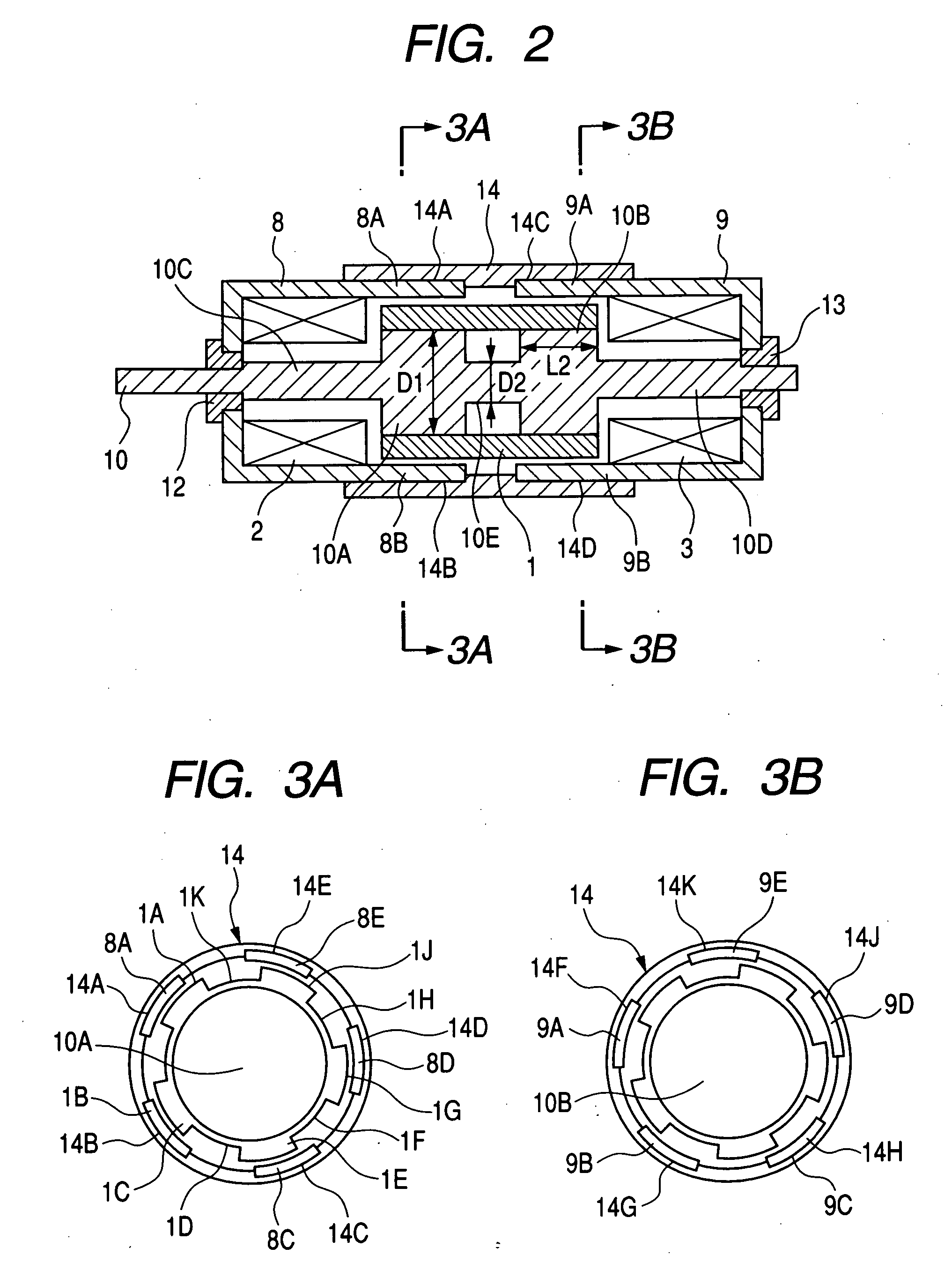
[0034] FIGS. 1 to 4A through 4H are diagrams related to Embodiment 1 of the present invention. Of the drawings, FIG. 1 is an exploded perspective view of a stepping motor, and FIG. 2 is an axial sectional view of the stepping motor of FIG. 1 in the assembled state. FIG. 3A is a sectional view taken along the line 3A-3A of FIG. 2, and FIG. 3B is a sectional view taken along the line 3B-3B of FIG. 2.

[0035] In the drawings, reference numeral 1 indicates a cylindrical magnet ring constituting a rotor. Its outer peripheral surface is circumferentially divided into n portions at equal intervals (n is an even number, which, in this embodiment, is 10). The divided portions are formed as radial protrusions and recesses (The protrusions are indicated by symbols 1A, 1C, 1E, 1G, and 1J, and the recesses are indicated by symbols 1B, 1D, 1F, 1H, and 1K), and are radially magnetized. In Embodiment 1, the inner peripheral surface is magnetized into an S-pole, and the outer peripheral surface, that...

embodiment 2

[0061]FIG. 5 is a sectional view of a stepping motor according to Embodiment 2 of the present invention. The components that are the same as those of Embodiment 1 are indicated by the same symbols, and a description thereof will be omitted.

[0062] In FIG. 5, reference numeral 15 indicates a first bobbin, around which the first coil 2 is wound. The first bobbin 15 is formed of a non-magnetic and non-conductive material, preventing inadvertent conduction between the first coil 2 and the first stator 8. The first bobbin 15 is fixed to the first stator 8, and the output shaft 10 is rotatably held by a hole 15A, providing the same function as the first bearing 12 of Embodiment 1. Reference numeral 16 indicates a second bobbin, around which the second coil 3 is wound. The second bobbin 16 is also formed of a non-magnetic and non-conductive material, preventing inadvertent conduction between the second coil 3 and the second stator 9. The second bobbin 16 is fixed to the second stator 9, an...

embodiment 3

[0064]FIG. 6 is a perspective view of the construction of a sheet-like magnet (permanent magnet) according to Embodiment 3 of the present invention. FIGS. 7A and 7B are sectional views of the output shaft of a stepping motor according to Embodiment 3 of the present invention, and a sheet-like magnet wound around the output shaft. More specifically, FIG. 7A is a sectional view of a portion near the first inner magnetic pole portion taken along a direction perpendicular to the axis, corresponding to FIG. 3A of Embodiment 1, and FIG. 7B is a sectional view of a portion near the second inner magnetic pole portion taken along a direction perpendicular to the axis, corresponding to FIG. 3B of Embodiment 1. The components that are the same as those of FIGS. 1 to 4A through 4H are indicated by the same symbols, and a detailed description thereof will be omitted.

[0065] In these drawings, reference numeral 20 indicates a sheet-like magnet formed of a flexible material, such as rubber, having...


PUM


Abstract

A stepping motor includes a magnet ring 1 whose outer peripheral surface is circumferentially divided to form radial protrusions and recesses and whose outer peripheral surface consists of a cylindrical permanent magnet magnetized to the same polarity, first and second cylindrical coils 2 and 3, a first outer magnetic pole portion 8 excited by the first coil, a second outer magnetic pole portion 9 excited by the second coil, and an output shaft 10 formed of a soft magnetic material and fixed to the inner peripheral portion of the magnet ring, the output shaft 10 being opposed to at least one of the first outer magnetic pole portion and the second outer magnetic pole portion in a predetermined axial range and equipped with an inner magnetic pole portion excited by at least one of the first coil and the second coil. Accordingly, a low-cost, high output, and high resolution stepping motor can be provided without hindering miniaturization.

Description

BACKGROUND OF THE INVENTION [0001] 1. Field of the Invention [0002] The present invention relates to a stepping motor of a cylindrical configuration applicable to a small apparatus, such as a photographing apparatus or a mobile phone. [0003] 2. Related Background Art [0004] A stepping motor having a reduced diameter about an output shaft and an enhanced output level has been proposed (refer to Japanese Patent Application Laid-Open No. H09-331666 (U.S. Pat. No. 5,831,356)). FIG. 10 shows an exploded perspective view of the stepping motor. FIG. 11 shows a sectional view of an assembled stepping motor taken along its axis. [0005]FIGS. 10 and 11 show a rotor 201 having a cylindrical shape which is formed of permanent magnet divided into four parts in a peripheral direction so as to alternately magnetize the parts into different polarities, a first coil 202 arranged adjacently to the rotor 201 in an axial direction, a second coil 203 similarly arranged adjacently to the rotor 201 in the ...

Claims


Application Information

Patent Timeline
IPC IPC(8): H02K37/00H02K37/14
CPCH02K37/14
Inventor AOSHIMA, CHIKARA
Owner CANON KK
Why Eureka
Try Eureka