Vehicle periphery monitoring system

a monitoring system and vehicle technology, applied in the direction of instruments, transportation and packaging, using reradiation, etc., can solve the problems of excessive monitoring of the driver by the system, and give the driver an adequate sense of safety, so as to achieve a high processing capacity and adequate sense of safety

Active Publication Date: 2005-10-20
DENSO CORP
View PDF4 Cites 157 Cited by
  • Summary
  • Abstract
  • Description
  • Claims
  • Application Information

AI Technical Summary

Benefits of technology

[0007] It is therefore an object of the present invention to provide a vehicle periphery monitoring system for giving the driver of a vehicle an adequate sense of safety by indicating whether a detected obstacle is a dangerous obstacle or a safe obstacle, and which can be realized without the need for a CPU having a high processing capability.
[0009] For example, if a person is detected at a distance greater than the preset distance from the vehicle, then the control unit indicates the detected person as a dangerous obstacle. If a pebble or a wheel block is detected at a distance greater than the preset distance from the vehicle, then the control unit either indicates the detected pebble or wheel block as a safe obstacle or inhibits the detected pebble or wheel block from being indicated. Therefore, the vehicle periphery monitoring system is able to indicate to the driver of the vehicle whether the detected obstacle is a dangerous obstacle or a safe obstacle. The driver is not kept excessively on full alert, i.e., is given an adequate sense of safety while the vehicle periphery monitoring system is operation. Since the vehicle periphery monitoring system acquires the height of the obstacle by performing the image processing process on the viewpoint-changed image, the vehicle periphery monitoring system is not required to perform the image processing process on the entire area of the captured image, and hence does not require a CPU having a high processing capability.
[0011] Alternatively, the indicating unit may comprise a display unit for displaying a bird's-eye image converted from the image captured by the imaging unit, and the control unit may control the display unit to display the detected obstacle as a safe obstacle overlappingly in the bird's-eye image displayed by the display unit if the acquired height of the detected obstacle is less than the preset height. Inasmuch as the obstacle is displayed overlappingly in the bird's-eye image, the driver is able to have an accurate sense of distance with respect to the obstacle.
[0013] The control unit may perform the image processing process on a portion of the viewpoint-changed image which is produced by changing the viewpoint of the image captured by the imaging unit, for thereby acquiring the height of the detected obstacle. As the image processing process is performed on a portion or limited area of the viewpoint-changed image, but not on the entire viewpoint-changed image, the processing load imposed on the vehicle periphery monitoring system for acquiring the height of the obstacle is relatively small.

Problems solved by technology

However, since sonic waves that are radiated into the detection range are vertically spread, if the detection distance is equal to or greater than a predetermined distance, the system tends to also detect undangerous obstacles on the ground, such as pebbles and wheel blocks, and indicate those detected undangerous obstacles to the driver of the vehicle.
Therefore, the system is liable to keep the driver excessively on full alert while in operation, i.e., to fail to give the driver an adequate sense of safety.

Method used


Image

  • Vehicle periphery monitoring system
  • Vehicle periphery monitoring system
  • Vehicle periphery monitoring system

Examples


Embodiment Construction

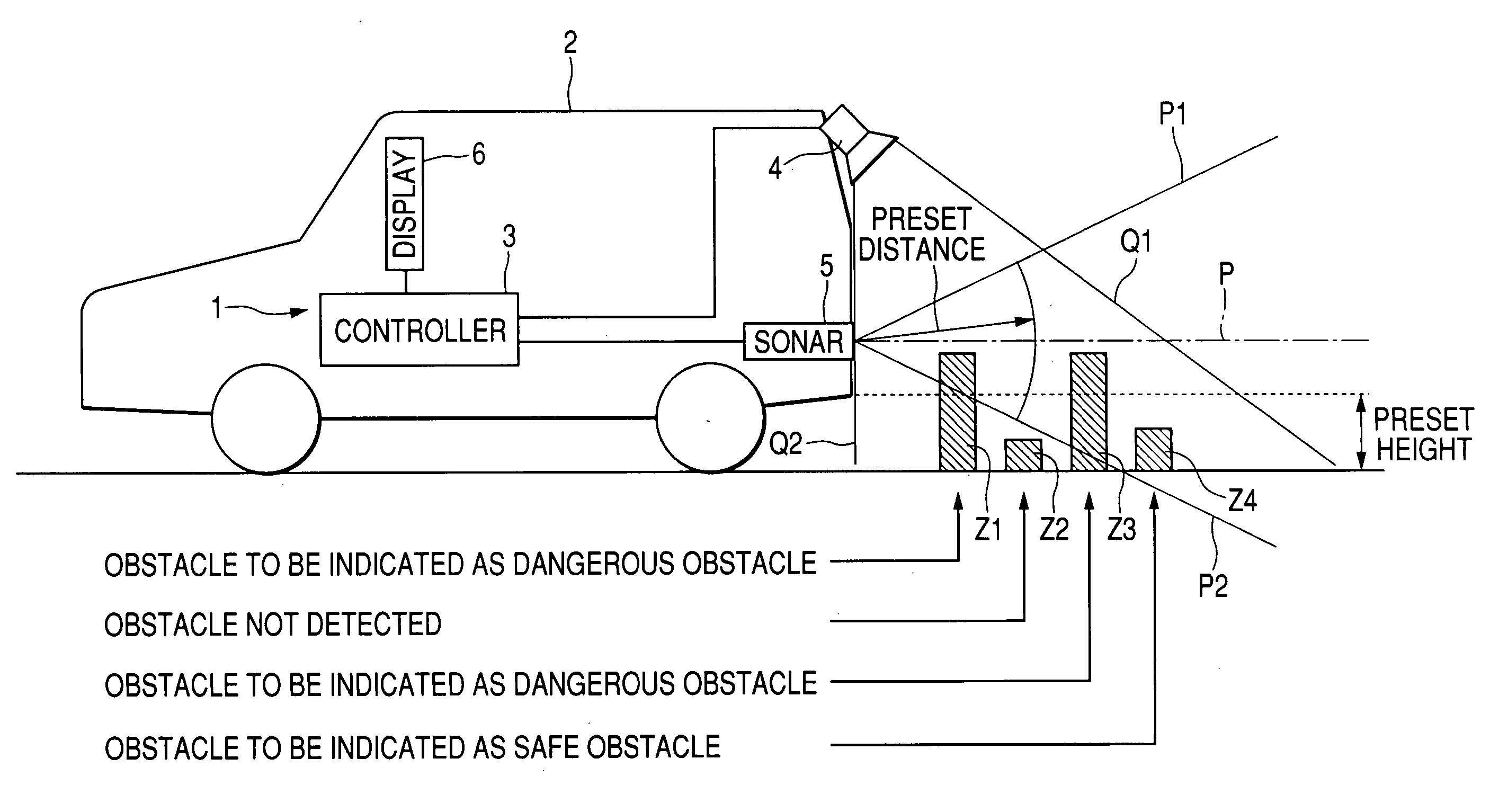
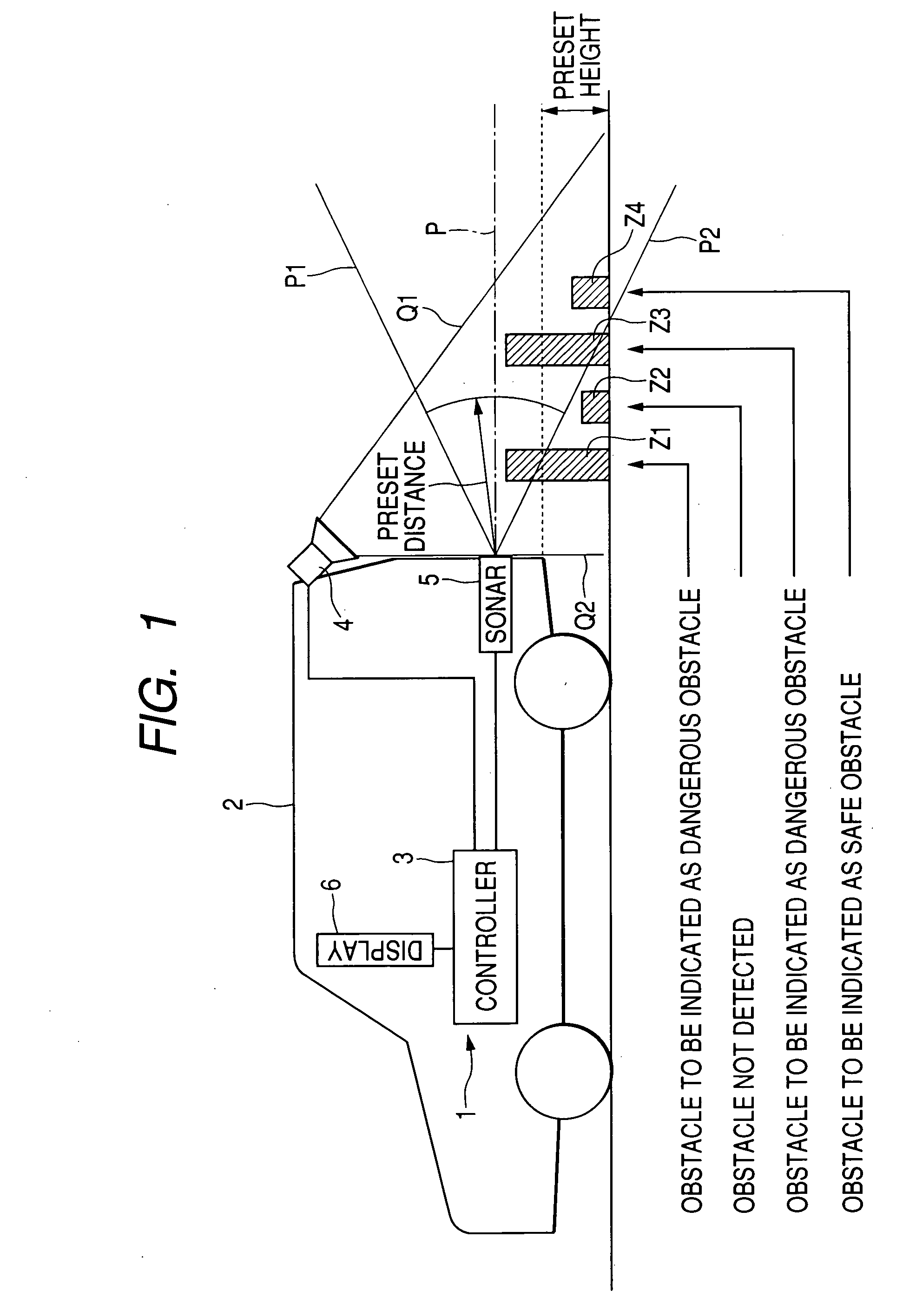
[0021]FIG. 1 schematically shows in side elevation a vehicle periphery monitoring system 1 according to an embodiment of the present invention.

[0022] As shown in FIG. 1, the vehicle periphery monitoring system 1 is mounted on a vehicle 2 such as an automobile and has a controller 3, a vehicle-mounted camera 4, a sonic sonar 5, and a display unit 6. The controller 3 serves as a control unit, the vehicle-mounted camera 4 as an imaging unit, the sonic sonar 5 as an obstacle detecting unit, and the display unit 6 as an indicating unit which may server as a display unit.

[0023] The controller 3 comprises a CPU, a RAM, a ROM, and I / O buses, and executes a control program to control the overall operation of the vehicle periphery monitoring system 1. The vehicle-mounted camera 4 is installed on an upper portion of the rear end of the vehicle 2. The vehicle-mounted camera 4 captures an, image of an area behind the vehicle 2, and outputs the captured image to the controller 3. The sonic sona...


PUM


Abstract

If the detected distance from a vehicle to a detected obstacle is equal to or greater than a preset distance, then a vehicle periphery monitoring system performs an image processing process on a captured image of the periphery of the vehicle to acquire the height of the vehicle. If the acquired height of the obstacle is less than a preset height, then the obstacle is displayed as a safe obstacle. If the acquired height of the obstacle is equal to or greater than the preset height, then the obstacle is displayed as a dangerous obstacle. The vehicle periphery monitoring system is able to indicate to the vehicle driver whether the detected obstacle is dangerous or safe. The vehicle periphery monitoring system is not required to perform the image processing process on the entire area of the captured image, and does not require a CPU having a high processing capability.

Description

CROSS REFERENCE TO RELATED DOCUMENT [0001] The present application claims the benefit of Japanese Patent Application No. 2004-109979 filed on Apr. 2, 2004, the disclosure of which is incorporated herein by reference. BACKGROUND OF THE INVENTION [0002] 1. Field of the Invention [0003] The present invention relates to a vehicle periphery monitoring system, and more particularly to a vehicle periphery monitoring system having an obstacle detecting unit for detecting the presence of an obstacle in the periphery of a vehicle and a controller for controlling an indicating unit to indicate the presence of an obstacle when the presence of such an obstacle is detected by the obstacle detecting unit. [0004] 2. Description of the Related Art [0005] Heretofore, there have been known various systems for detecting an obstacle that is present in the periphery of a vehicle and indicating the detected obstacle to the driver of the vehicle. One known system employs sonic waves to detect an obstacle a...

Claims


Application Information

Patent Timeline
Patent Type & Authority Applications(United States)
IPC IPC(8): B60Q1/00B60Q1/48B60R1/00G01S15/02G01S15/86G01S15/931G06K9/62G08G1/16
CPCB60Q9/005B60Q9/006B60R1/00B60R2300/207B60R2300/30B60R2300/301G08G1/16B60R2300/607B60R2300/802B60R2300/806G01S15/025G01S15/931B60R2300/305G08G1/165G08G1/168G01S15/86
Inventor SHIMIZU, HIROAKI
Owner DENSO CORP
Why Eureka
Try Eureka