
Constant current driving device, backlight light source device, and color liquid crystal display device

a technology of constant current driving and backlight light source, which is applied in the direction of static indicating devices, instruments, optics, etc., can solve the problems of complex driving circuit, increased cost, and difficult realization in an actual apparatus

Inactive Publication Date: 2005-10-20
SONY CORP
View PDF3 Cites 150 Cited by
  • Summary
  • Abstract
  • Description
  • Claims
  • Application Information

AI Technical Summary

Benefits of technology

[0013] In the present invention, a control circuit performs control to bypass a driving current flowing through other elements than an arbitrary element to be measured via switching elements respectively connected in parallel with a plurality of the elements connected in series with each other and pass a measuring driving current through only the element to be measured. It is thus possible to identify an element at a faulty position by detecting the driving current flowing through the plurality of elements connected in series with each other by a detecting circuit.
[0015] Further, the control circuit performs control to bypass the driving current flowing to the element at the faulty position at all times by operating a switching element formed by a transistor connected in parallel with the element at the faulty position, the element at the faulty position being identified by the detecting circuit, in synchronism with PWM driving by the pulse width modulation constant current driving circuit. It is thereby possible to bypass the element current at the faulty position via the switching element.

Problems solved by technology

Therefore the driving circuit is complex and requires a high cost (see Japanese Patent Laid-Open No. 2001-272938, for example).
To detect these failures requires employment of a method of driving each LED element by an independent driving circuit and construction of a system for feeding back a state of operation of each element at all times, which increases cost and is thus difficult to realize in an actual apparatus.
Therefore, when a part is unlit due to a failure, unevenness or the like occurs, which is not comfortable to the eye.
A matrix driving LSI or the like for high power driving in LED driving devices for a lighting purpose has not been created, and is practically disadvantageous in terms of cost.
However, in the series connection form, when a failure occurs in an individual light emitting diode and the failure is a disconnection, all light emitting diodes in the row are not lit, thus causing considerable color unevenness.

Method used


Image

  • Constant current driving device, backlight light source device, and color liquid crystal display device
  • Constant current driving device, backlight light source device, and color liquid crystal display device
  • Constant current driving device, backlight light source device, and color liquid crystal display device

Examples


Embodiment Construction

[0032] Preferred embodiments of the present invention will hereinafter be described in detail with reference to the drawings. It is to be noted that the present invention is not limited to the following examples, and that of course the present invention is susceptible of arbitrary changes without departing from the spirit of the present invention.

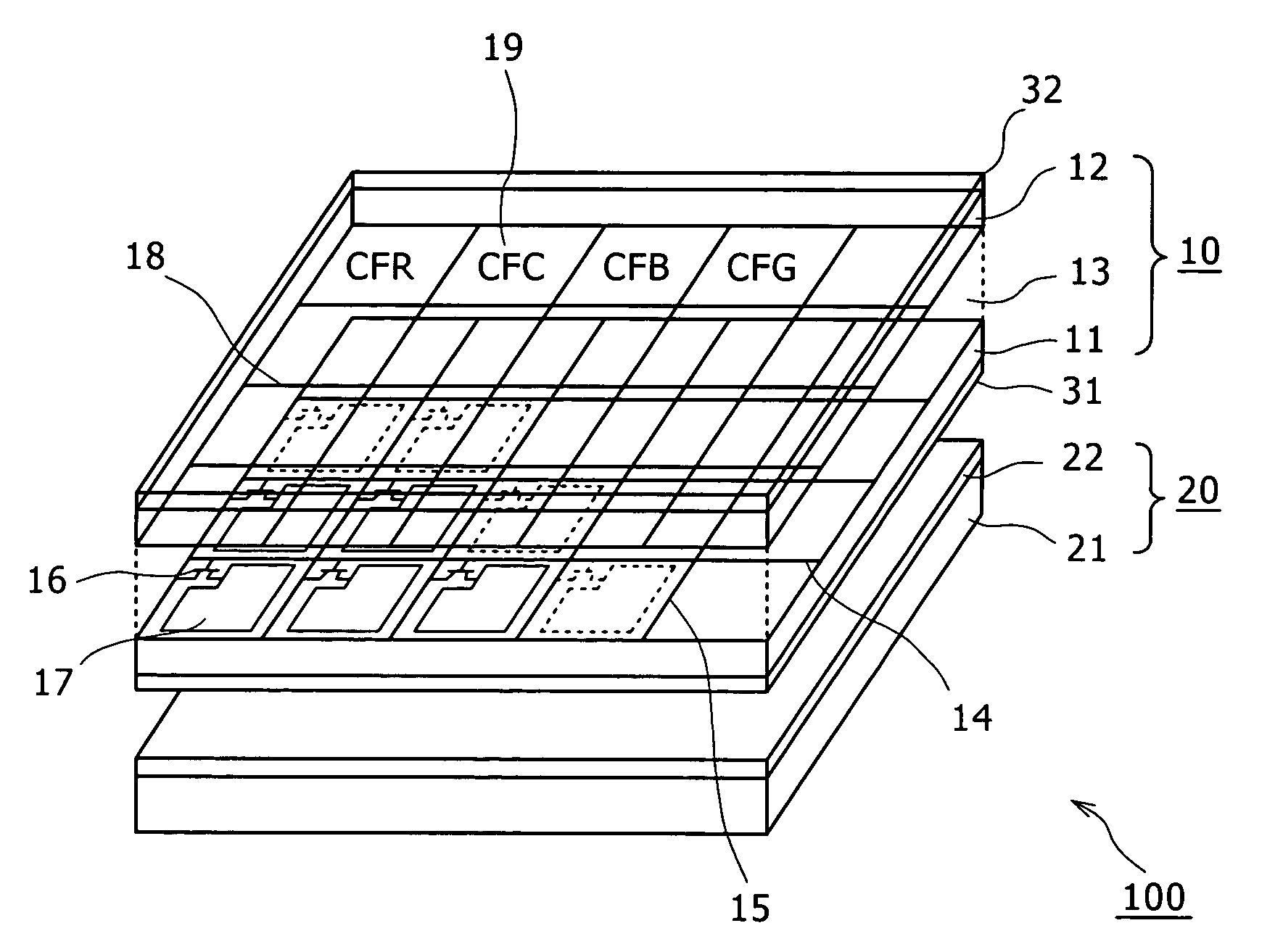
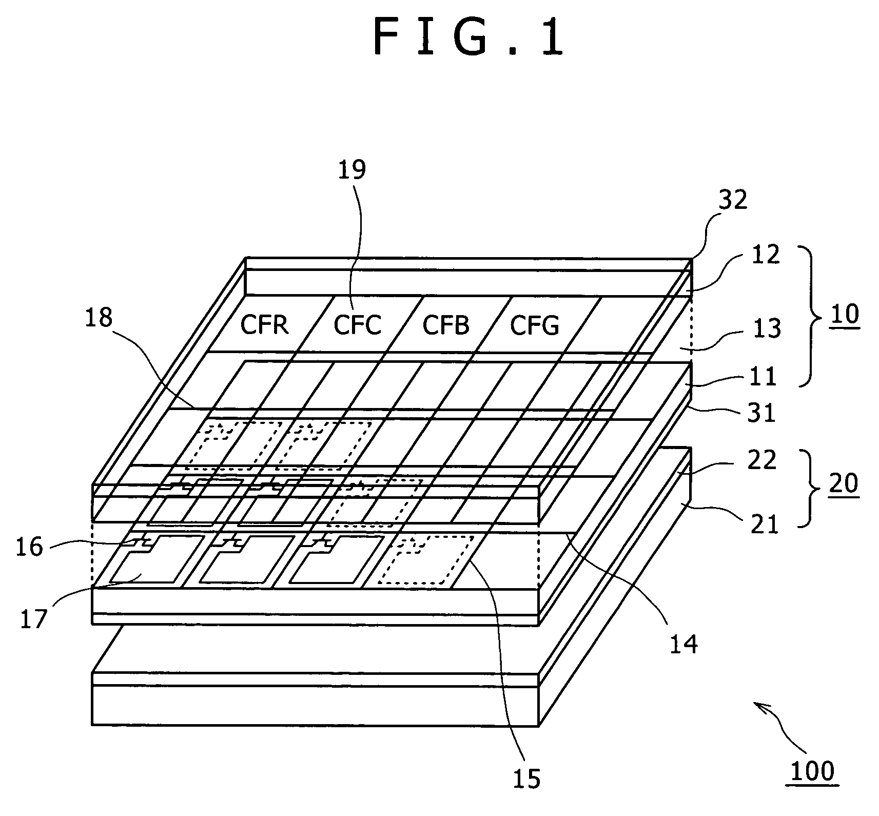
[0033] The present invention is applied to a backlight type color liquid crystal display device 100 of a configuration as shown in FIG. 1, for example.

[0034] The color liquid crystal display device 100 comprises a transmissive type color liquid crystal display panel 10 and a backlight light source device 20 provided on a back side of the color liquid crystal display panel 10.

[0035] The transmissive type color liquid crystal display panel 10 has a structure in which two transparent substrates (a TFT substrate 11 and a counter electrode substrate 12) formed of glass or the like are opposed to each other, and a liquid crystal layer 13 is pr...


PUM


Abstract

A constant current driving device for constant current driving of a plurality of elements connected in series with each other by a pulse width modulation constant current driving circuit includes: switching elements respectively connected in parallel with the plurality of elements connected in series with each other; a control circuit for performing control to bypass a driving current flowing through the other elements than an arbitrary element to be measured via the respective switching elements and pass a measuring driving current through only the element to be measured; and a detecting circuit for identifying an element at a faulty position by detecting the driving current flowing through the plurality of elements connected in series with each other.

Description

BACKGROUND OF THE INVENTION [0001] The present invention relates to a constant current driving device for constant current driving of a plurality of elements, for example light emitting diodes (LEDs) connected in series with each other by a pulse width modulation constant current driving circuit, a backlight light source device driven by the constant current driving device, and a color liquid crystal display device. [0002] As is typified by liquid crystal panels and plasma display panels (PDPs), there has recently been a trend toward thinner displays. Among the displays, many displays for mobile use are liquid crystal panels, which are desired to have faithful color reproducibility. While a mainstream backlight for liquid crystal panels is a CCFL (Cold Cathode Fluorescent Lamp) type using a fluorescent tube, mercury-less backlights have been requested from an environmental point of view. Light emitting diodes and the like are considered to be promising as a light source to replace t...

Claims


Application Information

Patent Timeline
IPC IPC(8): G09G3/34G02F1/13357G09G3/36G09G5/00H01L33/00H05B44/00
CPCG09G3/3406G09G3/342G09G2300/0452G09G2320/064G09G2330/08H05B33/089G09G2360/145H05B33/0818H05B33/083H05B33/0857G09G2330/12H05B45/48H05B45/20H05B45/54H05B45/3725H05B45/10G02F1/133G09G3/32
Inventor FURUKAWA, NORIMASA
Owner SONY CORP
Learn More