Recessed downlight Mounting fixture

Active Publication Date: 2005-10-20
SIGNIFY NORTH AMERICA CORP
View PDF17 Cites 8 Cited by
  • Summary
  • Abstract
  • Description
  • Claims
  • Application Information

AI Technical Summary

Benefits of technology

[0010] With regard to the foregoing, the present invention eliminates the oversights, difficu

Problems solved by technology

Since the parts are formed separately, the material costs are expensive due to the large amounts of waste generated in producing each part separately.
As a result, the costs for manufacturing includes a large amount of wasted material as each part is

Method used


Image

  • Recessed downlight Mounting fixture
  • Recessed downlight Mounting fixture
  • Recessed downlight Mounting fixture

Examples


Embodiment Construction

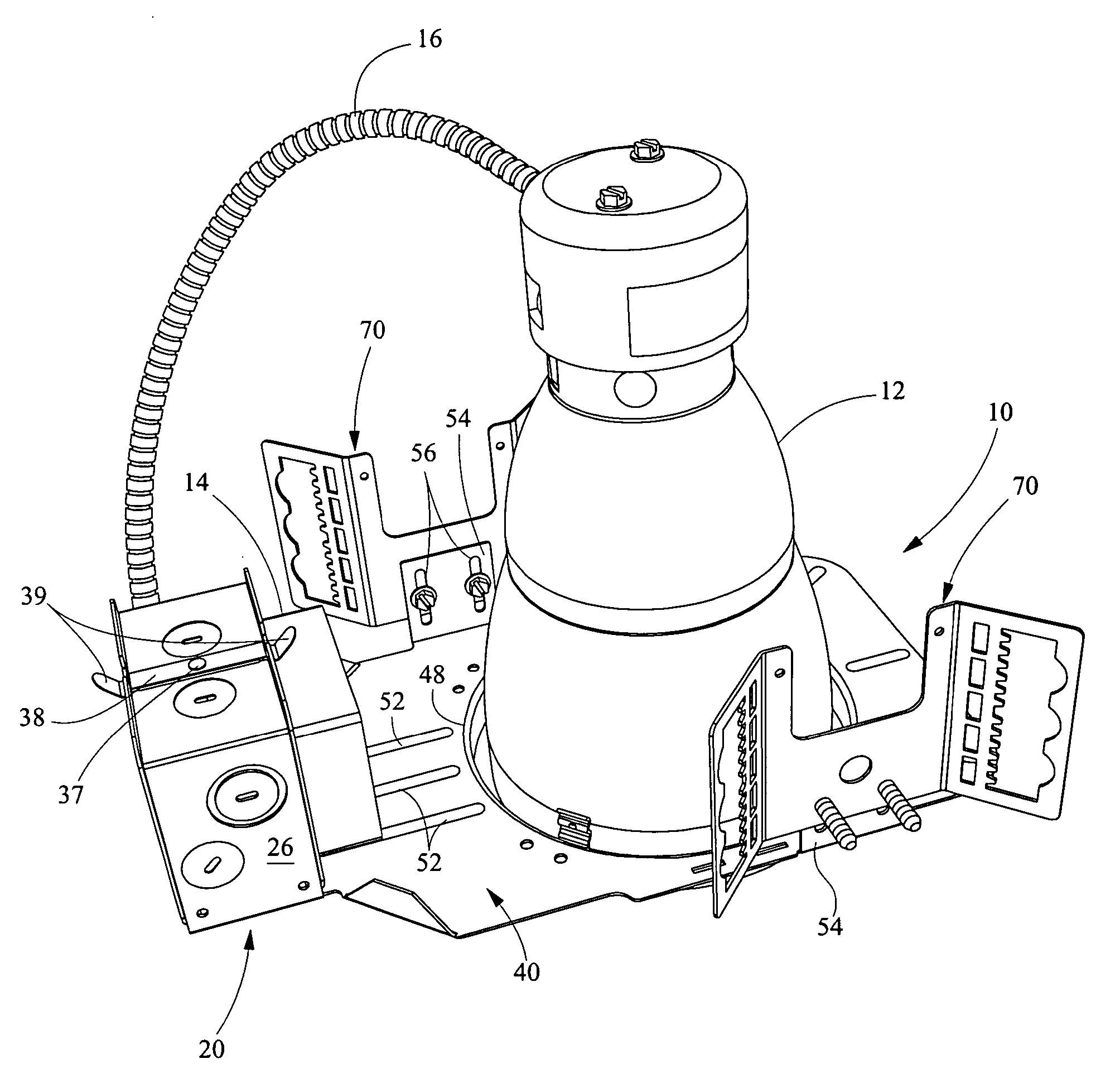
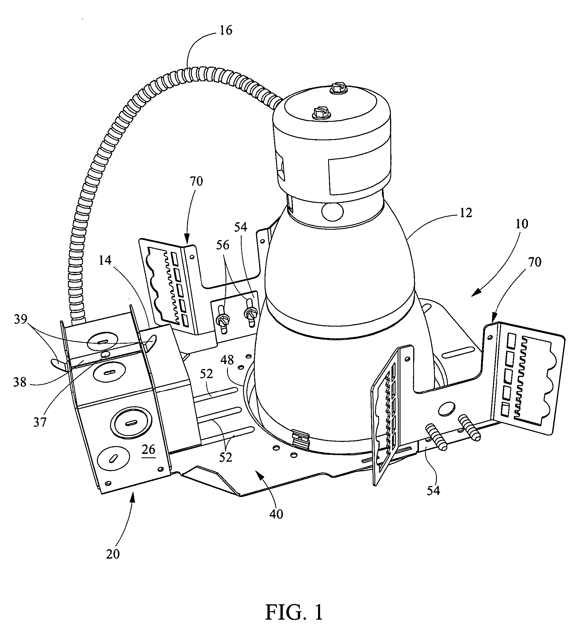
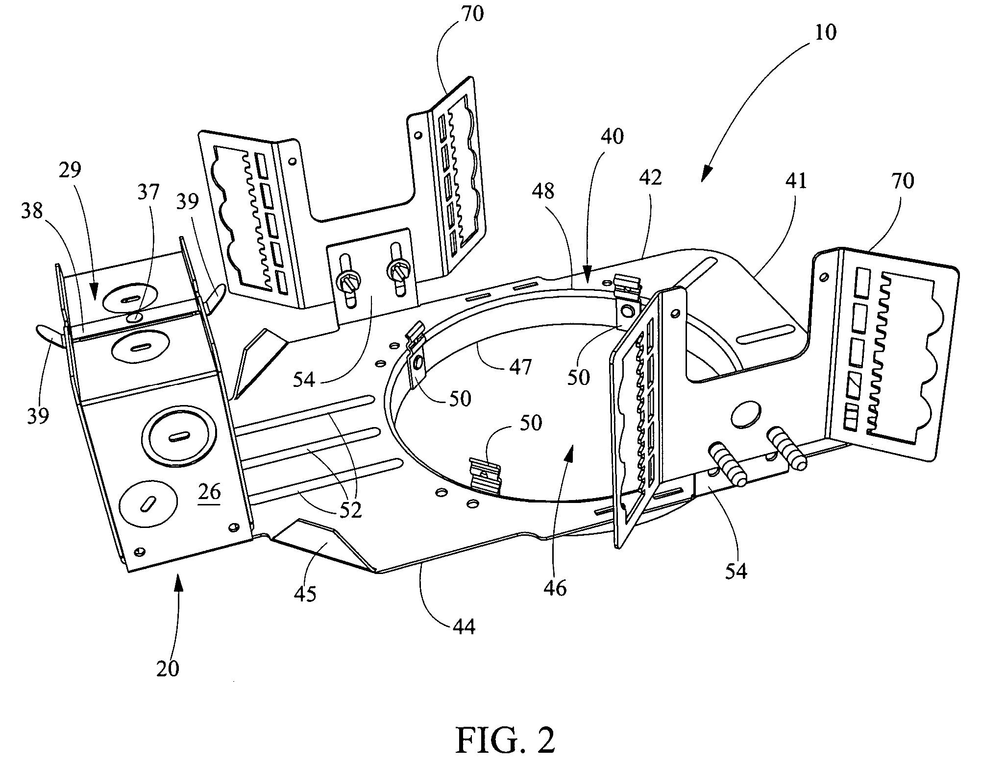
[0022] Referring now in detail to the drawings, wherein like numerals indicate like elements throughout the several views, there are shown in FIGS. 1 through 4 various aspects of a recessed downlight mounting fixture both before and after manufacture. The fixture includes a fixture plate and various assembly parts all formed from a single tooling and a single sheet of material or blank in order to improve efficiency, reduce waste, and reduce cost of materials utilized in manufacturing the mounting fixture.

[0023] Referring initially to FIG. 1, a perspective view of the complete recessed downlight mounting fixture 10 is depicted. The fixture or rough-in section 10 is shown including a lamp housing 12, ballast 14 and a conduit 16 extending between the lamp housing 12 and a junction box 20 connected to the ballast 14. The ballast 14 provides power for the lamp (not shown) within the lamp housing 12. The downlight mounting fixture 10 may be positioned within a ceiling of a room in order...


PUM


Abstract

A recessed downlight mounting fixture having a fixture plate formed from a blank, the fixture plate having at least one aperture for receiving a lamp housing, a junction box formed from said the blank and foldably integral with said the fixture plate, at least one junction box door formed from the blank with the fixture plate, and, at least one mounting bar bracket formed from the blank.

Description

CROSS REFERENCE TO RELATED APPLICATION [0001] Not applicable STATEMENT REGARDING FEDERALLY SPONSORED RESEARCH OR DEVELOPMENT [0002] Not applicable REFERENCE TO SEQUENTIAL LISTINGS, ETC. [0003] Not applicable BACKGROUND [0004] 1. Field of the Invention [0005] The present invention relates to a recessed downlight mounting FIXTURE. More specifically, the present invention relates to recessed downlight mounting fixture comprising a plurality of parts defining an assembly which are simultaneously formed from a single tooling. [0006] 2. Background of the Invention [0007] Recessed downlighting has been ever increasing in popularity for use in both commercial and residential structures and as a result, competition has increased dramatically in this lighting area. To that end, manufacturers continue to search for ways to decrease costs for manufacturing and assembly in order to increase profits and decrease consumer costs. [0008] Current recessed lighting frames are assembled utilizing vario...

Claims


Application Information

Patent Timeline
IPC IPC(8): F21K2/00F21V19/00F21V21/04
CPCF21V21/04Y10T29/5313Y10T29/53174
Inventor CZECH, KENNETH
Owner SIGNIFY NORTH AMERICA CORP
Why Eureka
Try Eureka