Plastic mount system for cellular phone or personal electronic device attachment

a technology for cellular phones and electronic devices, applied in the field of plastic clip mount systems, can solve the problems of metal adversely affecting radiation absorption and possible re-transmission

Inactive Publication Date: 2005-10-20
FINDINGS & MFG
View PDF3 Cites 3 Cited by
  • Summary
  • Abstract
  • Description
  • Claims
  • Application Information

AI Technical Summary

Benefits of technology

[0012] It is another object of the present invention to provide a lock or latch which prohibits movement of the actuator-plunger until the user releases the latch.

Problems solved by technology

Although “jaw style” belt clips with metal leaf springs are known, the metal adversely effects radiation absorption and possible re-transmission.

Method used


Image

  • Plastic mount system for cellular phone or personal electronic device attachment
  • Plastic mount system for cellular phone or personal electronic device attachment
  • Plastic mount system for cellular phone or personal electronic device attachment

Examples


Embodiment Construction

[0029] The present invention relates to a plastic mount system for a cellular telephone attachment system having a button mount or a similarly configured mount system for a button sub-system for a personal electronic device and a method of mounting.

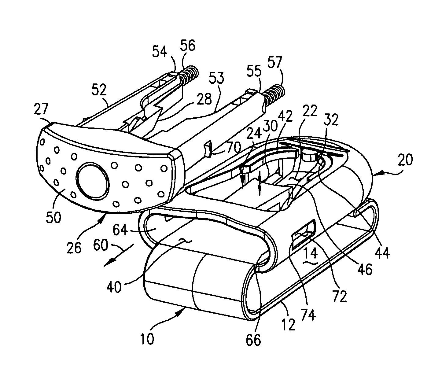
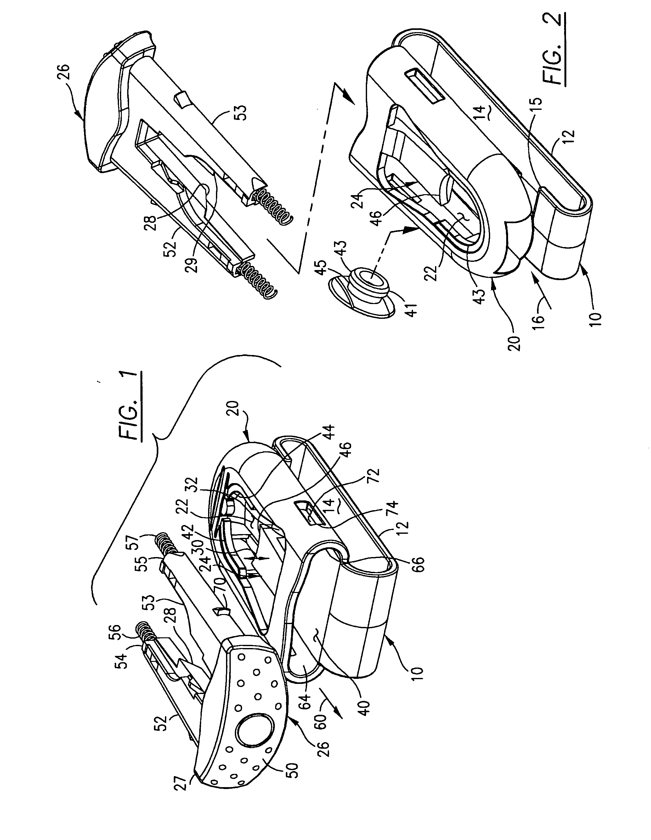
[0030]FIG. 1 shows one embodiment of clip mount 10 including a belt loop 12 having a belt loop cavity 14 therein. Similar numerals designate similar items throughout all the figures. Belt loop 12, as shown in FIG. 2, has a free end 15 that permits the user to slip a strap or a belt as shown by arrow 16 into belt or strap cavity 14. Alternatively, the user could slip free end 15 inside his or her pants or purse edge and carry the mount system thereon.

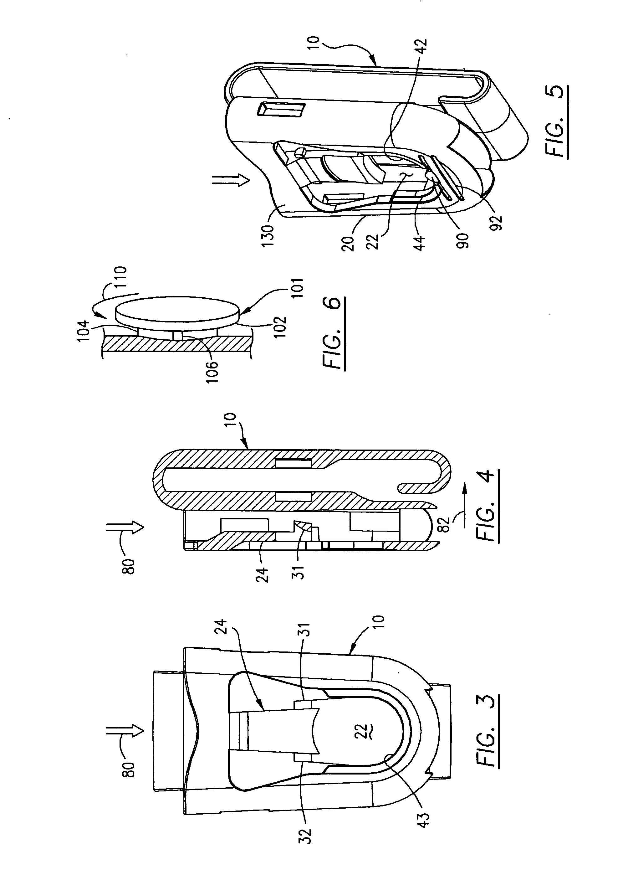
[0031] Although the figures show a specific manufactured embodiment for the clip mount, other structures may utilize portions of the clip mount 10 invention, which embodiment includes three (3) basic elements which are clip body 20, defining a locking cavity 22, a resilient tongue 24, an act...


PUM


Abstract

The clip-mount operates with a button sub-mount system and includes a body defining a locking cavity for the button and a resilient locking tongue therein. The tongue biases the button into a locking position with a cam surface. A movable cam actuator on the body includes another cam surface which coacts with the first cam permitting the tongue to flex or unlock. An enhancement includes both an unlocking cam and a second locking cam structure. The method includes biasing the button to a locking position and moving one cam over another thereby flexing the tongue from a locked to a button release position. The actuator maybe biased outboard or upward via a plastic spring on the actuator-plunger. A plastic leaf spring may be provided between a clip arm and the button clip mount body. A lock or latch may lock on the actuator-plunger.

Description

[0001] This is a continuation in part patent application based upon and claiming priority from application Ser. No. 10 / 791,128 filed Mar. 2, 2004, now pending which is a regular patent application based upon and claiming the benefit of provisional patent application Ser. No. 60 / 534,206, filed Jan. 5, 2004. [0002] The present invention relates to a plastic mount system for a cellular telephone attachment system with a button mount (or a mount for a personal electronic device) and a method therefor.BACKGROUND OF THE INVENTION [0003] Many cell phone users utilize a clip mount which may be attached to his or her belt, purse or other strap. These clip mount systems coact with a clip-on structure which is removably attached to the generally rectangular body of the cellular telephone. The sub-system attachment to the cellular telephone includes a button which protrudes from the backside of the sub-system. The present invention is a plastic clip mount system for this type of button mount. T...

Claims


Application Information

Patent Timeline
Patent Type & Authority Applications(United States)
IPC IPC(8): A45F5/02H04M1/00H04M1/04
CPCA45F5/02A45F5/021H04M1/04A45F2200/0516A45F2005/026
Inventor TAGES, FERNANDOGORADESKY, HAROLD S.
Owner FINDINGS & MFG
Why Eureka
Try Eureka