Rigging system for loudspeakers

a loudspeaker and rigging technology, applied in the direction of transducer details, electrical apparatus casings/cabinets/drawers, loudspeaker casing supports, etc., can solve the problems of large adjustment range, large adjustment range, and relatively difficult process, so as to achieve greater range and small adjustment increments. , the effect of easy assembly

Active Publication Date: 2005-10-20
MEYER SOUND LABORATORIES
View PDF16 Cites 36 Cited by
  • Summary
  • Abstract
  • Description
  • Claims
  • Application Information

AI Technical Summary

Benefits of technology

[0005] There is a need for a rigging system for loudspeakers having splay angle adjustment capabilities that is relatively easy to

Problems solved by technology

This process turns out to be relatively difficult and leads to misses in the hole alignme

Method used


Image

  • Rigging system for loudspeakers
  • Rigging system for loudspeakers
  • Rigging system for loudspeakers

Examples


Embodiment Construction

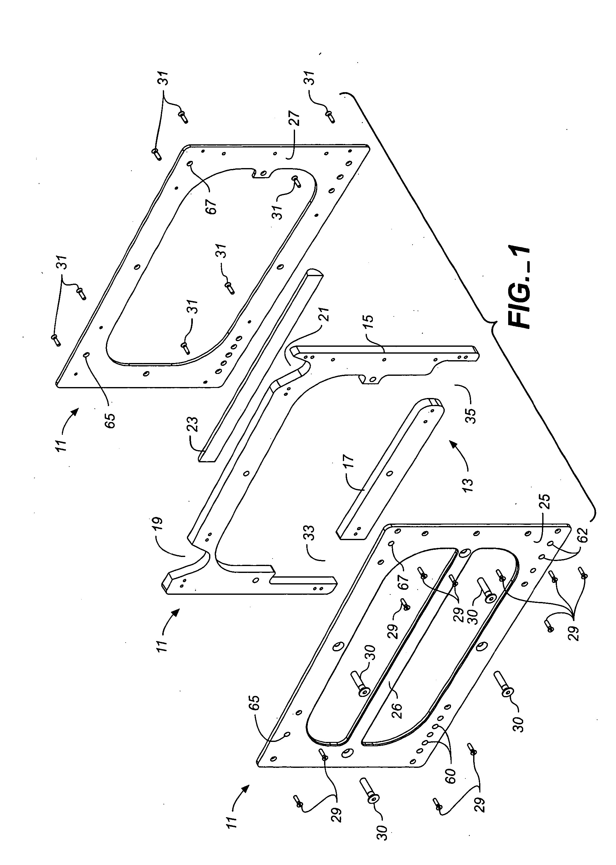
[0019] The preferred frame structure of the rigging side frame of the invention is disclosed in FIG. 1. The frame structure is comprised of a frame assembly denoted by the numeral 11 having a center core structure 13 which includes upper perimeter core section 15 and a lower cross-bar center core section 17. The upper perimeter center core section includes two cutouts 19, 21, which provide cradling surfaces for link guide channels of the assembled frame assembly as hereinafter described. The center core structure of the assembly is sandwiched between front and back side plates 25, 27 that are secured to the center core sections by suitable attachment screws 29, 30, 31. When assembled, the open regions 33, 35 between the bottom ends of upper perimeter core section 15 and the lower cross-bar 17, form additional guide channels for stowing the links of the side frame as also hereinafter described.

[0020] With further reference to FIG. 1, the front side plate 25 of the frame assembly is ...


PUM


Abstract

A side frame for a loudspeaker rigging system has a frame structure mountable to the side of a loudspeaker, and links associated with the frame structure for linking together the corners of the frame structures of vertically adjacent side frames. The links associated with each side frame structure include a pivot link and splay adjustment link, each of which has a top extended end and a base end with a seating edge. Guide channels, which are located in the top corner regions of the frame structure to receive the base ends of a pivot link and splay adjustment link associated with a vertically adjacent side frame, have seating surfaces that conform to the seating edges at the base ends of the pivot and splay adjustment link. When base ends of these links seat in the guide channels, pin holes in the base end of the links self-align with pin holes in the corners of the frame structure for easy insertion locking pins. The extended end of the splay adjustment link further includes at least two, and preferably an array of pin holes which can selectively be matched with one pin hole within a row of pin holes in a bottom corner region of the side frame to permit adjustments of the splay angle over a range of angles. Suitably, two rows of pin holes are provided in the top extended end of the splay adjustment link to permit multiple and incrementally small splay angle adjustments. In the preferred embodiment, the frame structure is comprised of an assembly of parts comprised of a center core structure sandwiched between two side plates.

Description

CROSS-REFERENCE TO RELATED APPLICATIONS [0001] This application claims the benefit of U.S. Provisional Application No. 60 / 536,429 filed Jan. 13, 2004, and U.S. Provisional Application No. 60 / 548,364 filed Feb. 27, 2004.BACKGROUND [0002] The present invention relates to loudspeaker rigging systems and more particularly to rigging hardware for suspending a stacked array of loudspeakers of a sound reinforcement system at a predetermined location relative to an audience. The present invention has particular application in rigging a stacked array of loudspeakers wherein a vertical display between loudspeakers is desired to achieve a desired coverage and acoustic performance. [0003] Sound systems for large venues typically involve the suspension or “flying” of stacks of loudspeakers in vertical arrays to achieve a desired acoustic output and coverage for a large audience. Such vertical stacks of loudspeakers are typically suspended and held together by rigging systems which can be attache...

Claims


Application Information

Patent Timeline
IPC IPC(8): H04R1/02H04R1/40H04R9/06
CPCH04R1/403H04R1/026
Inventor MONITTO, JOHNMCGHEE, JOHNMARSHALL, DEAN
Owner MEYER SOUND LABORATORIES
Why Eureka
Try Eureka