Apparatus and method for detecting defects in periodic pattern on object

a technology of periodic pattern and object, applied in the field of periodic pattern defect detection on objects, can solve problems such as the inability to detect defects with accuracy, and achieve the effect of high accuracy

Inactive Publication Date: 2005-10-20
DAINIPPON SCREEN MTG CO LTD
View PDF2 Cites 34 Cited by
  • Summary
  • Abstract
  • Description
  • Claims
  • Application Information

AI Technical Summary

Benefits of technology

[0007] In this apparatus, since the position of the first differential image is adjusted relatively to the second differential image on the basis of the first positional difference vector or the second positional difference vector, it is possible to detect a defect in a periodic pattern on the object with high accuracy.
[0010] Since the first differential image and the second differential image are generated on the basis of the second image, it is possible to detect a defect in a periodic pattern on the object with high accuracy.

Problems solved by technology

As a result, for example, when it is intended to sequentially acquire three images and sequentially generate two differential images to compare these differential images with each other, since there is a difference in position between the corresponding pixels of the two differential images, it is impossible to detect any defect with accuracy.

Method used


Image

  • Apparatus and method for detecting defects in periodic pattern on object
  • Apparatus and method for detecting defects in periodic pattern on object
  • Apparatus and method for detecting defects in periodic pattern on object

Examples


Embodiment Construction

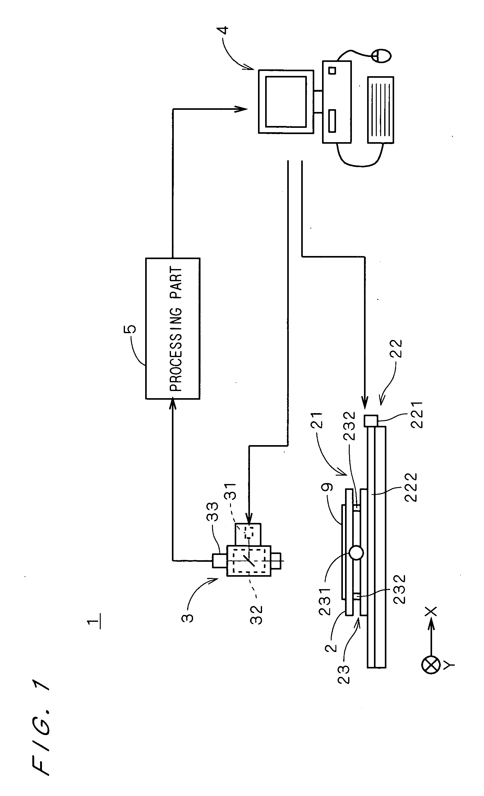
[0028]FIG. 1 is a view showing a construction of a defect detection apparatus 1 in accordance with the first preferred embodiment of the present invention. The defect detection apparatus I comprises a stage 2 for holding a substrate 9 on which a periodic pattern is formed, an image pickup part 3 for picking up an image of the substrate 9 to acquire image data of the substrate 9 and a stage driving part 21 for moving the stage 2 relatively to the image pickup part 3.

[0029] The stage driving part 21 has an X-direction moving mechanism 22 for moving the stage 2 in the X direction of FIG. 1 and a Y-direction moving mechanism 23 for moving the stage 2 in the Y direction. The X-direction moving mechanism 22 has a motor 221 to which a ball screw (not shown) is connected and with rotation of the motor 221, the Y-direction moving mechanism 23 moves along guide rails 222 in the X direction of FIG. 1. The Y-direction moving mechanism 23 has the same structure as the X-direction moving mechani...


PUM

PropertyMeasurementUnit
grayscaleaaaaaaaaaa
defect detectionaaaaaaaaaa
distanceaaaaaaaaaa

Abstract

In a defect detection apparatus, images of first to third inspection areas on a substrate are picked up to acquire first to third images. A positional difference acquisition part (51) acquires a first difference vector between the first image and the second image and a second difference vector between the second image and the third image. A differential image generation part (52) generates a first differential image between the first image and the second image while adjusting a position of the first image to the second image on the basis of the first difference vector and a second differential image between the second image and the third image while adjusting a position of the second image to the third image on the basis of the second difference vector. Then, a position of the second differential image is adjusted to the first differential image on the basis of the second difference vector and the second differential image after position adjustment and the first differential image are compared with each other, to detect a defect in a periodic pattern on the substrate with high accuracy.

Description

BACKGROUND OF THE INVENTION [0001] 1. Field of the Invention [0002] The present invention relates to a technique for detecting a defect in a periodic pattern on an object, which is used, for example, for appearance inspection of semiconductor substrates, printed circuit boards and the like. [0003] 2. Description of the Background Art [0004] A variety of inspection methods have been used, conventionally, in a field of appearance inspection of semiconductor substrates, printed circuit boards and the like. Japanese Patent Application Laid Open Gazette No. 60-57929 (Document 1), for example, discloses a method of detecting a defect in an inspection image. In the method, the binary inspection image is moved to a plurality of positions relatively to the binary reference image, the number of pixels having different values between a binary inspection image and a binary reference image are counted up in the relative positions, a positional difference vector (hereinafter, referred to simply a...

Claims


Application Information

Patent Timeline
Patent Type & Authority Applications(United States)
IPC IPC(8): G01N21/956G06K9/00G06T7/00
CPCG06T2207/30148G06T7/0004
Inventor ONISHI, HIROYUKISASA, YASUSHI
Owner DAINIPPON SCREEN MTG CO LTD
Why Eureka
Try Eureka