Splint or support with quick location technique

a technology of positioning and splints, applied in the field of orthopaedic splints or supports, can solve the problems of splints falling off, difficult to maintain the appropriate position for each particular injury during application, etc., and achieve the effect of quick and easy adjustment of position and effective holding

Inactive Publication Date: 2005-10-20
KAUPTHING BANK
View PDF39 Cites 25 Cited by
  • Summary
  • Abstract
  • Description
  • Claims
  • Application Information

AI Technical Summary

Benefits of technology

[0004] In accordance with the present invention a splint, blank, or main support is provided with primary tacking arrangements to help hold the splint, blank, or main support in place, allowing the physician or technician the use of two free hands for quickly and easily adjusting the position of the splint, blank, or main support if necessary without removing or loosening the primary tacking arrangements. The physician or technician then applies a secondary, more supportive securing arrangements to effectively hold the splint, blank, or main support to the injured part of the patient's anatomy.
[0016] It is further noted that the use of a layer of UBL or hook-receivable material has the additional advantage of restricting the flow of the hardenable material, as set forth in, for example, U.S. Pat. No. 6,824,522 (Henderson, et al.), titled “Hardenable Orthopaedic Supports,” whose entire contents are hereby incorporated by reference.

Problems solved by technology

Frequently, lengthy splints must be used to properly immobilize the injured limb, and gravity causes one end or the other of the splint to fall away from the anatomy or merely shift away from the proper position.
If one person is attempting to apply the splint, it is difficult to maintain the appropriate position for each particular injury during application.

Method used


Image

  • Splint or support with quick location technique
  • Splint or support with quick location technique
  • Splint or support with quick location technique

Examples


Embodiment Construction

[0030] While the specification describes particular embodiments of the present invention, those of ordinary skill can devise variations of the present invention without departing from the inventive concept.

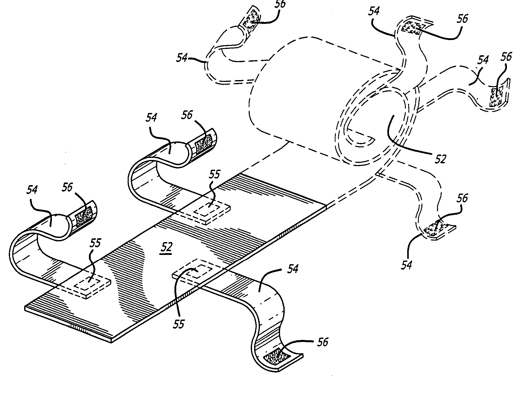
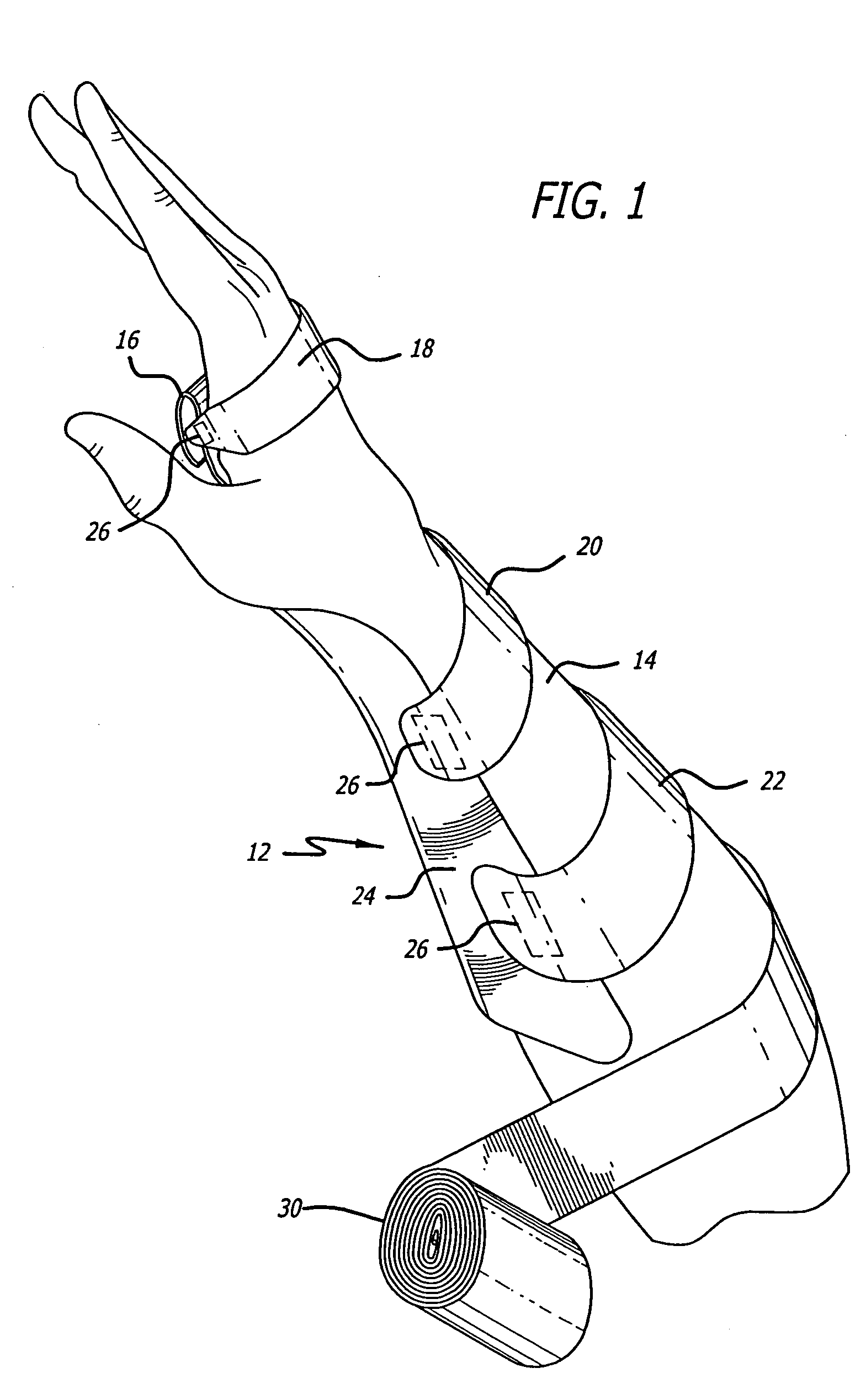
[0031] Referring more particularly to the drawings, FIG. 1 shows a splint or brace 12 mounted on the forearm 14 of a patient. The main part of the brace 12 is optionally folded over at reference numeral 16 at the palm of the patient's hand, and strap 18 extends over the back of the hand. The straps 18, 20 and 22 are secured to or are part of the main part 24 of the splint, and are provided with hook type fastener 26 on the underside of straps 18, 20 and 22 as shown in FIG. 1. The areas of the splint 12 underlying patches 26 are of hook receivable type material, so the straps 18, 20 and 22 are held or “tacked” in place as the splint 12 is applied. With the splint being held onto the forearm in an adjustable manner, the physician or medical technician can readily position the splin...


PUM


Abstract

An orthopaedic splint apparatus and technique involving the use of a water hardenable blank with (1) primary tacking arrangements for adjustably holding the splint or support in place after it has been activated and placed on the injured part of the anatomy, and may also include (2) secondary, functional arrangements for holding the splint firmly in place following accurate mounting and location of the splint on the injured part of the anatomy. The tacking arrangements may involve the use of lateral extensions from the main body of the splint with hook and loop type fasteners or adhesive associated with the extensions for holding the splint onto the injured part of the anatomy.

Description

CROSS-REFERENCE TO RELATED APPLICATIONS [0001] This is a continuation-in-part application of co-pending parent application Ser. No. 10 / 828,744, filed Apr. 20, 2004, whose entire contents are hereby incorporated by reference.BACKGROUND OF THE INVENTION [0002] This invention relates to orthopaedic splints or supports. [0003] In the field of hardenable orthopaedic splints and supports, the splints are normally rectangular in shape and are held on to the anatomy by a finishing tape of some kind wrapped along the entire length of the splint. To function properly, both the splint and finishing tape are soft and supple in order to conform to the contours of the anatomy. During application of the splint, it is necessary that the limb be held in a variety of positions. Frequently, lengthy splints must be used to properly immobilize the injured limb, and gravity causes one end or the other of the splint to fall away from the anatomy or merely shift away from the proper position. If one person...

Claims


Application Information

Patent Timeline
Patent Type & Authority Applications(United States)
IPC IPC(8): A61F5/00A61F5/01
CPCA61F5/00A61F5/05841A61F5/05825A61F5/0118
Inventor GRIM, TRACY E.HENDERSON, WENDYIGLESIAS, JOSEPH M.CAMPOS, MICHAELDOUBLEDAY, WALTER D.LONG, KELLY M.
Owner KAUPTHING BANK
Why Eureka
Try Eureka