
Fastener for lightweight concrete roof systems

a technology of lightweight concrete and fasteners, which is applied in the direction of roofs, ceilings, buildings, etc., can solve the problems of failure of lightweight concrete roof systems

Inactive Publication Date: 2007-11-27
GEMBALA HENRY +2
View PDF17 Cites 21 Cited by
  • Summary
  • Abstract
  • Description
  • Claims
  • Application Information

AI Technical Summary

Benefits of technology

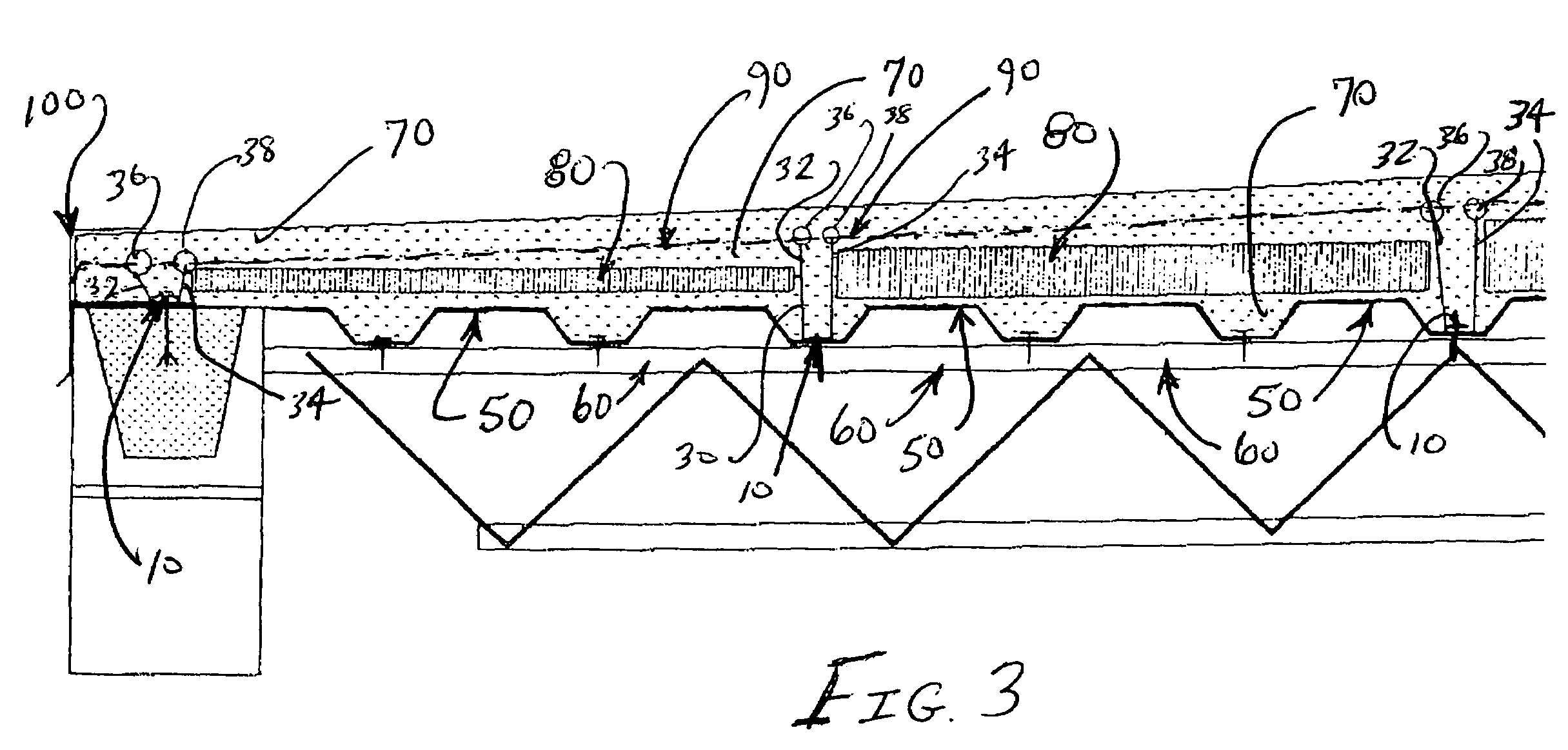
[0010]In use, the base element of the fastening device is mechanically fastened to the bar joist of the roof system, through the steel deck. After application of a slurry of lightweight concrete over the top of the steel deck, a steel welded wire reinforcement fabric is laid on the top of the lightweight concrete layer. The terminal distal ends of the fastening device are secured to the steel welded wire reinforcement fabric to effectively hold the lightweight concrete layer sandwiched between the steel welded wire reinforcement fabric and the steel deck.

Problems solved by technology

Presently, the failure of lightweight concrete roof systems is often a result of separation of the lightweight concrete layer from the steel deck caused by wind sheer and flexing of the underlying steel deck.
When the steel deck is caused to flex, separation often occurs between the steel deck and the lightweight concrete.

Method used


Image

  • Fastener for lightweight concrete roof systems
  • Fastener for lightweight concrete roof systems
  • Fastener for lightweight concrete roof systems

Examples


Embodiment Construction

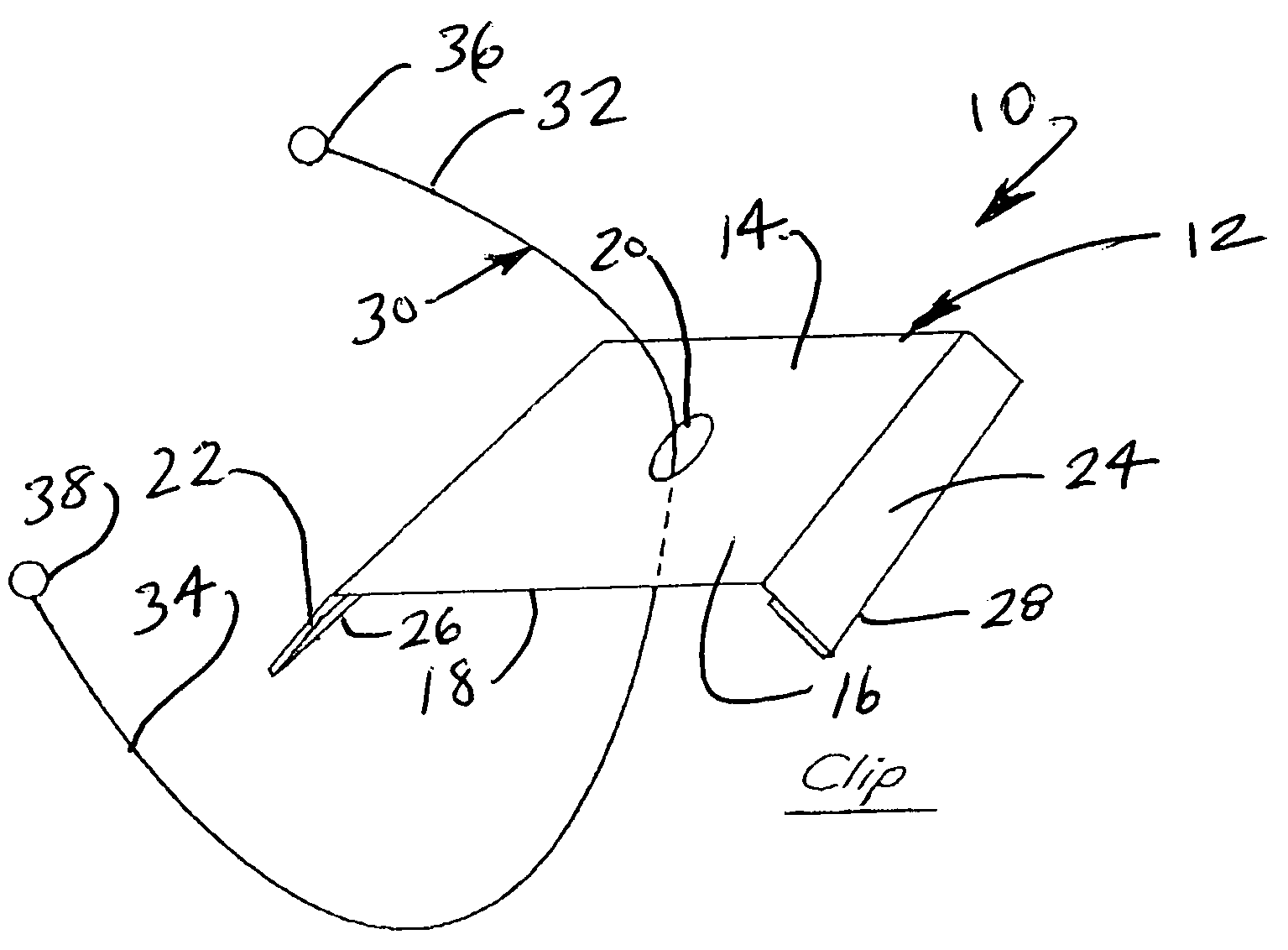
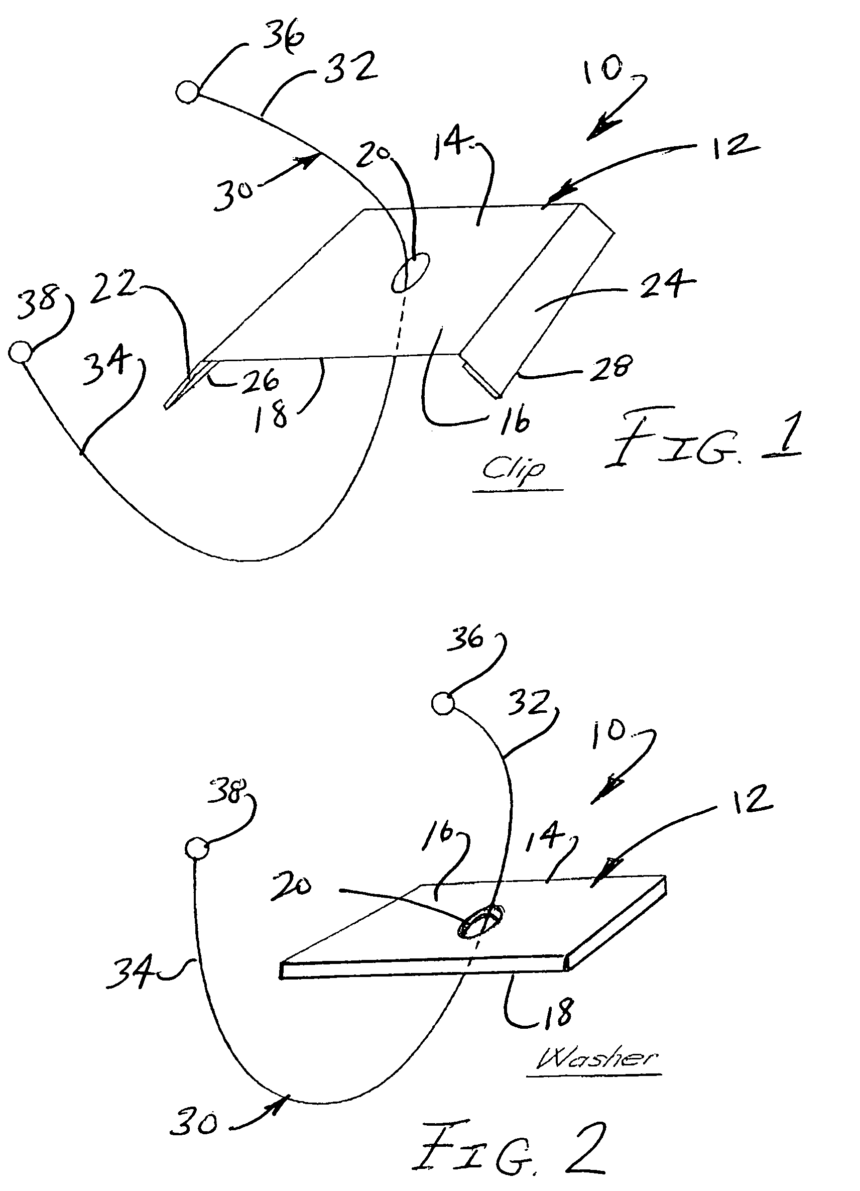
[0016]Referring initially to FIGS. 1 and 2, the fastening device of the present invention is shown in accordance with several embodiments and is generally indicated as 10. In each embodiment, the fastening device 10 includes a base element 12 having a substantially flat portion 14 with a top side 16 and a bottom side 18. An hole 20 may be formed through the flat portion 14 to accommodate passage of a mechanical fastener, such as a TEK screw, for fastening the base element 12 to the deck structure of the roof system. In each of the embodiments of FIGS. 1 and 2, the fastening device 10 further includes a wire tie 30. The wire tie 30 is preferably welded or otherwise secured to the base element 12 and includes opposite leg portions 32, 34 extending upwardly from the base element 12 and terminating at respective distal ends 36, 38. In a preferred embodiment, the distal ends 36, 38 are formed in a ring or loop for grasping and securing the leg portions 32, 34 to a steel welded wire reinf...


PUM


Abstract

A device for use in the installation of lightweight concrete roof systems includes a base element having a substantially flat portion and a wire tie. The wire tie extends from the base element and terminates at opposite ends which may be formed in a ring or loop. In use, the base element is mechanically fastened to the bar joist, through the steel deck, of the roof system. The terminal ends of the wire tie are secured to steel-welded wire reinforcement fabric overlying a layer of lightweight concrete, thereby securing the lightweight concrete to the steel deck of the roof system and preventing separation of the lightweight concrete due to external forces such as wind sheer.

Description

[0001]This Application is based on Provisional Patent Application Ser. No. 60 / 467,202 filed on May 1, 2003.BACKGROUND OF THE INVENTION[0002]1. Field of the Invention[0003]The present invention relates to a device for use in the installation of lightweight concrete roof systems and, more particularly, to a device for securing lightweight concrete to an underlying steel deck of a roof system, thereby preventing separation of the lightweight concrete from the underlying roof structure when subjected to external forces, such as wind sheer.[0004]2. Discussion of the Related Art[0005]Certain roof systems, such as those typically found in the construction of a commercial building, involve the installation of a steel deck over a bar joist. The steel deck is attached to the underlying bar joist by direct welding, welding with washers, or the use of mechanical fasteners such as TEK screws. Once the steel deck is properly attached to the underlying bar joist, the top of the steel deck is prepa...

Claims


Application Information

Patent Timeline
Patent Type & Authority Patents(United States)
IPC IPC(8): E04B1/38E04B9/00E04C5/00E04F13/04E04B5/40E04D7/00E04D13/16
CPCE04B5/40E04D13/1668E04D13/1643E04D7/00
Inventor GEMBALA, HENRYGEMBALA, DAVIDSTEIER, TOM
Owner GEMBALA HENRY
Learn More