
Quick-release chuck having compact collar

a quick-release chuck and compact collar technology, which is applied in the field of quick-release chucks, can solve the problems of requiring a complex and expensive assembly process, significant gap between the chuck and the housing of the power tool, etc., and achieves the effect of reducing the necessary length of the chuck, enhancing safety, and low profile shap

Inactive Publication Date: 2003-09-09
CREDO TECH CORP
View PDF20 Cites 23 Cited by
  • Summary
  • Abstract
  • Description
  • Claims
  • Application Information

AI Technical Summary

Benefits of technology

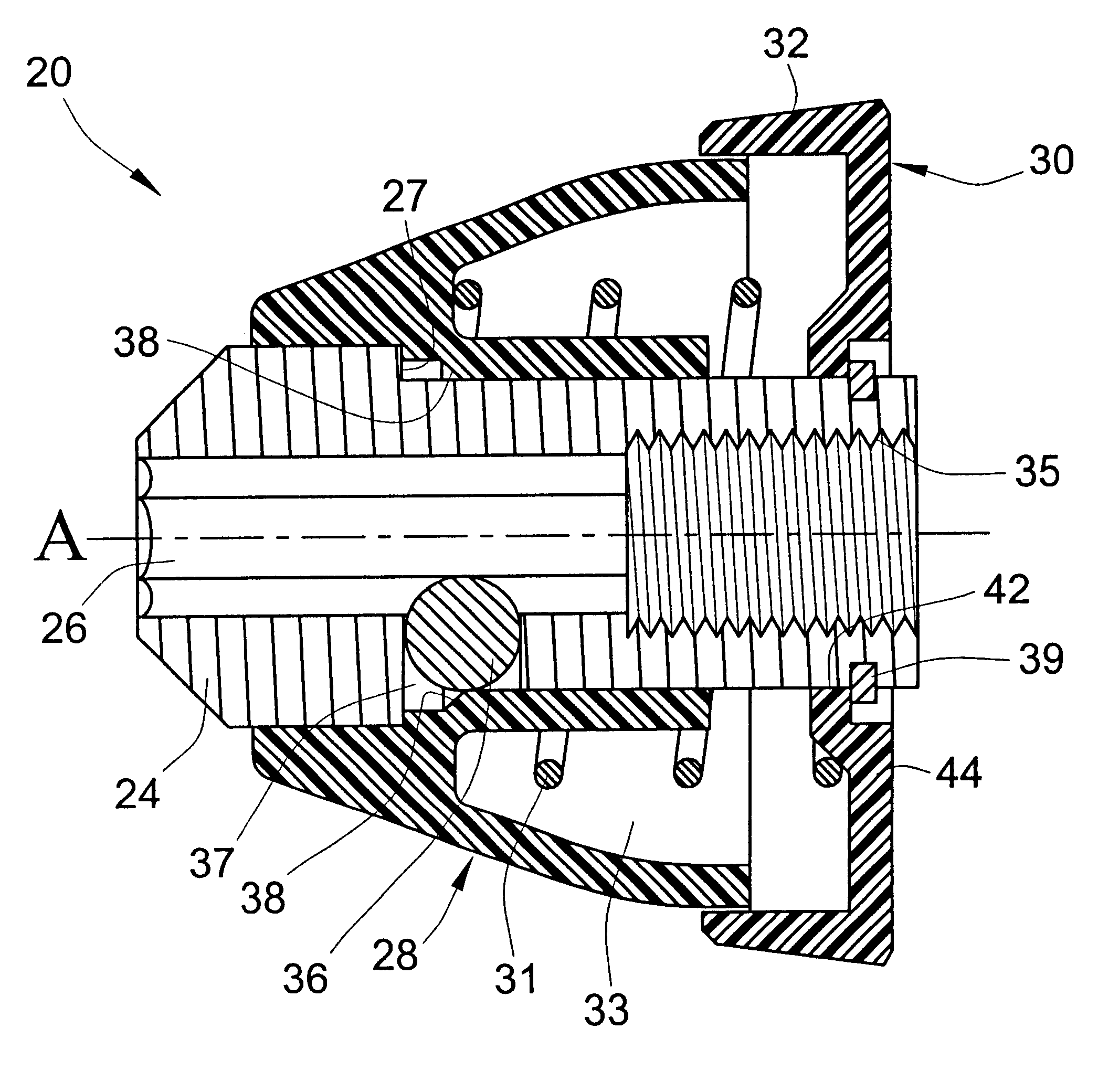
The present invention provides an improved quick-release chuck having a compact profile and view components. In an embodiment, the chuck includes a barrel configured to be mounted to a rotatable shaft of a rotary power tool. The barrel has an axial bore for receiving and holding a tool bit. A moveable sleeve fits concentrically around the barrel and is axially moveable relative thereto for actuating one or more locking member, such as a radially-moveable ball positioned in a hole through the barrel to releasably secure the tool bit in the bore. To release the locking member, the moveable sleeve is axially retractable toward the power tool. The chuck additionally includes a collar which has a low-profile shape. In particular, the collar has a central flange which is disposed around the barrel, a planar web portion which extends radially outwardly from the central flange and an outer guide flange that extends from an outer periphery of the planar portion in a direction away from the rotary power tool. The outer guide flange is shaped to receive and guide a proximal portion of the moveable sleeve when the sleeve is pulled to release the tool bit. The outer guide flange also serves to cover a gap between a proximal side of the moveable sleeve and the planar web portion of the collar. The collar is secured to the barrel in a position closely proximal to the power tool housing. The structure of the collar minimizes the gap between the chuck and the housing of the rotary power tool, advantageously enhancing safety and minimizing the necessary length of the chuck.
In an embodiment, the moveable sleeve, spring, collar, and retainer ring are easily assembled onto the barrel in a stackable manner from the proximal end of the chuck. The collar acts as a cap which compresses the biasing member and effectively holds the components of the chuck in an assembled condition. The stackable configuration advantageously facilitates an assembly of the chuck in a simple and efficient manner.

Problems solved by technology

At least some conventional quick-release chucks have a configuration such that, when mounted to a rotatable shaft of a power tool, a significant gap exists between the chuck and a housing of the power tool.
Also, conventional chucks have included a large number of components, requiring a complex and expensive assembly process.

Method used


Image

  • Quick-release chuck having compact collar
  • Quick-release chuck having compact collar
  • Quick-release chuck having compact collar

Examples


Embodiment Construction

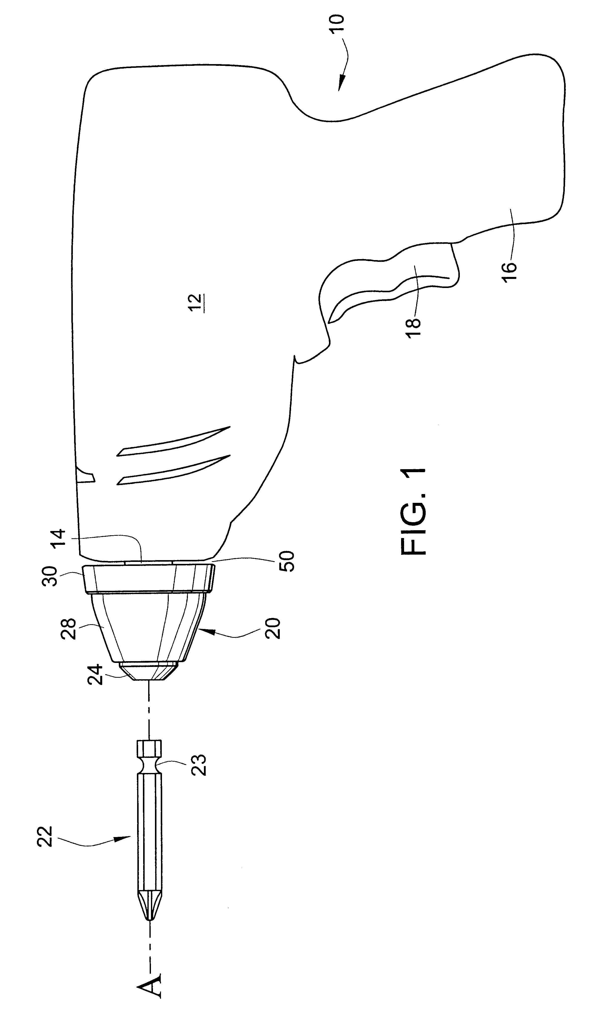
Now turning to the drawings, wherein like numerals designate like components, FIG. 1 illustrates a rotary power tool 10 having a housing 12. The housing 12 contains an electric motor (not shown) operable to rotatably drive a shaft 14 that rotates about an axis A. In the illustrated embodiment, the housing 12 is shaped to include a handle 16 to be gripped by a user and a trigger switch 18 that selectively actuates the motor.

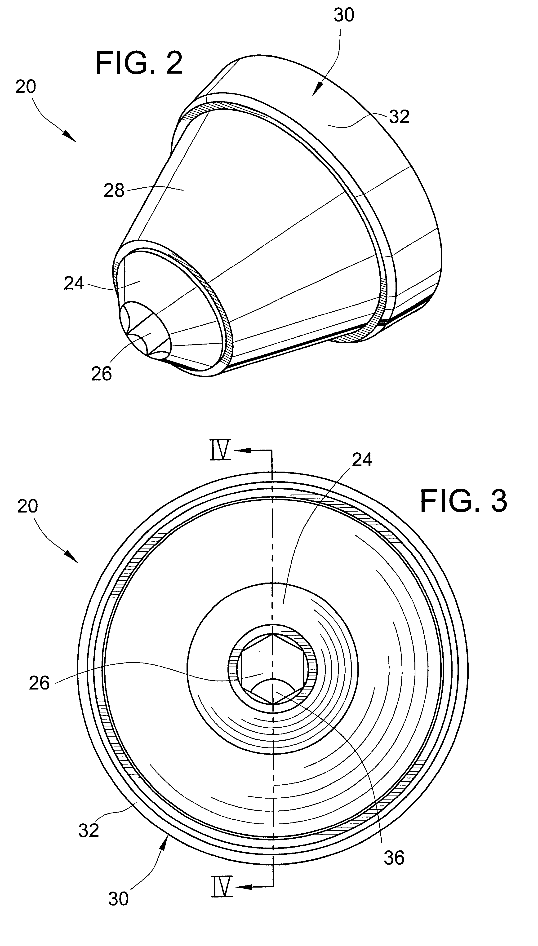
FIG. 1 also illustrates a quick-release chuck 20 mounted to the shaft 14. The chuck 20 is operable to securely hold a tool bit 22 driven by the rotary power tool 10. In the illustrated embodiment, the tool bit 22 is configured as a cross-headed screwdriver tip, however, those skilled in the art will recognize that the chuck 20 is useful to hold any other type of rotating tool bit, such a flat headed screwdriver, boring tool, grinding bit, wire brush, socket, drill bit, etc. The tool bit is preferably of a type that has a locking recess 23.

Referring to FIGS. 1-3, t...


PUM


Abstract

The quick-release chuck for a rotary power tool is provided for holding a tool bit. The chuck includes a barrel having an axial bore to receive the tool bit and an axially movable sleeve operable to position a locking member to selectively lock or release the tool bit. A proximal end of the chuck near the housing of the power tool includes a low-profile collar which holds a spring in compression against the sleeve, biasing the sleeve in a distal, locked position. The components of the chuck may advantageously be assembled in a stacked manner. The low-profile collar permits the chuck to occupy a minimal length and to be positioned with a minimal separation from the housing of the power tool for enhanced safety.

Description

The present invention generally relates to rotary tools and more particularly relates to a quick-release chuck having an axially slidable member to actuatably release or hold a tool bit.Chucks for rotary tools are generally known. A chuck is securable to a rotatable shaft of a power tool and is operable to hold a replaceable tool bit. Known quick-release chucks have a bore in which a tool bit is received, and the chuck includes a locking element which is selectively actuatable to secure or release the tool bit.Conventional quick-release chuck structures have implemented components which occupy a significant axial length. It is desirable to provide a chuck that has a low-profile, compact structure with a minimal length.At least some conventional quick-release chucks have a configuration such that, when mounted to a rotatable shaft of a power tool, a significant gap exists between the chuck and a housing of the power tool. It is desirable to minimize the gap for safety and compactness...

Claims


Application Information

Patent Timeline
IPC IPC(8): B23B31/10B23B31/107
CPCB23B31/1071Y10S279/905Y10T279/17752Y10T279/17811Y10T279/17743
Inventor PJEVACH, ROBERTGROTH, BRADY
Owner CREDO TECH CORP
Learn More