Polishing apparatus and method

a technology of polishing apparatus and polishing method, which is applied in the direction of lapping machines, grinding machine components, manufacturing tools, etc., to achieve the effect of high precision and high precision

Inactive Publication Date: 2009-04-07
SHIN-ETSU HANDOTAI CO LTD
View PDF19 Cites 22 Cited by
  • Summary
  • Abstract
  • Description
  • Claims
  • Application Information

AI Technical Summary

Benefits of technology

[0028]It is accordingly an object of the present invention to provide a polishing apparatus and a polishing method both capable of performing polishing a work (such as a wafer) with high efficiency and high precision, a novel work holding plate effectively holding a work and an adhering method for a wafer capable of adhering the work on the work holding plate with high precision.
[0069]High precision wafer polishing finish becomes possible by polishing a silicon wafer which is adhered and held on a work holding plate by means of the above described method for adhering a work of the present invention. At this time, the use of the above described polishing apparatus is very effective for realizing high precision polishing finish implementing the fundamental concept of the present invention that in polishing action an amount of deformation of the polishing table in a direction normal to an upper surface thereof and / or an amount of deformation of the work holding plate in a direction normal to a work holding surface thereof is kept to be 100 μm or less, preferably 30 μm or less.

Problems solved by technology

In polishing finish of a wafer, as described above, there have been various factors that are obstacles against achievement of high precision finish thereof meeting higher level of device fabrication techniques now and in the future, not only in connection with deformation by various causes of a polishing apparatus: particularly a work holding plate directly holding a wafer, which is a to-be-processed work, and a polishing table on which a polishing cloth in contact with the wafer is adhered and variations in operation of the apparatus, but also in connection with an adhering method for pasting the wafer on the work holding plate.

Method used


Image

  • Polishing apparatus and method
  • Polishing apparatus and method
  • Polishing apparatus and method

Examples


example 1

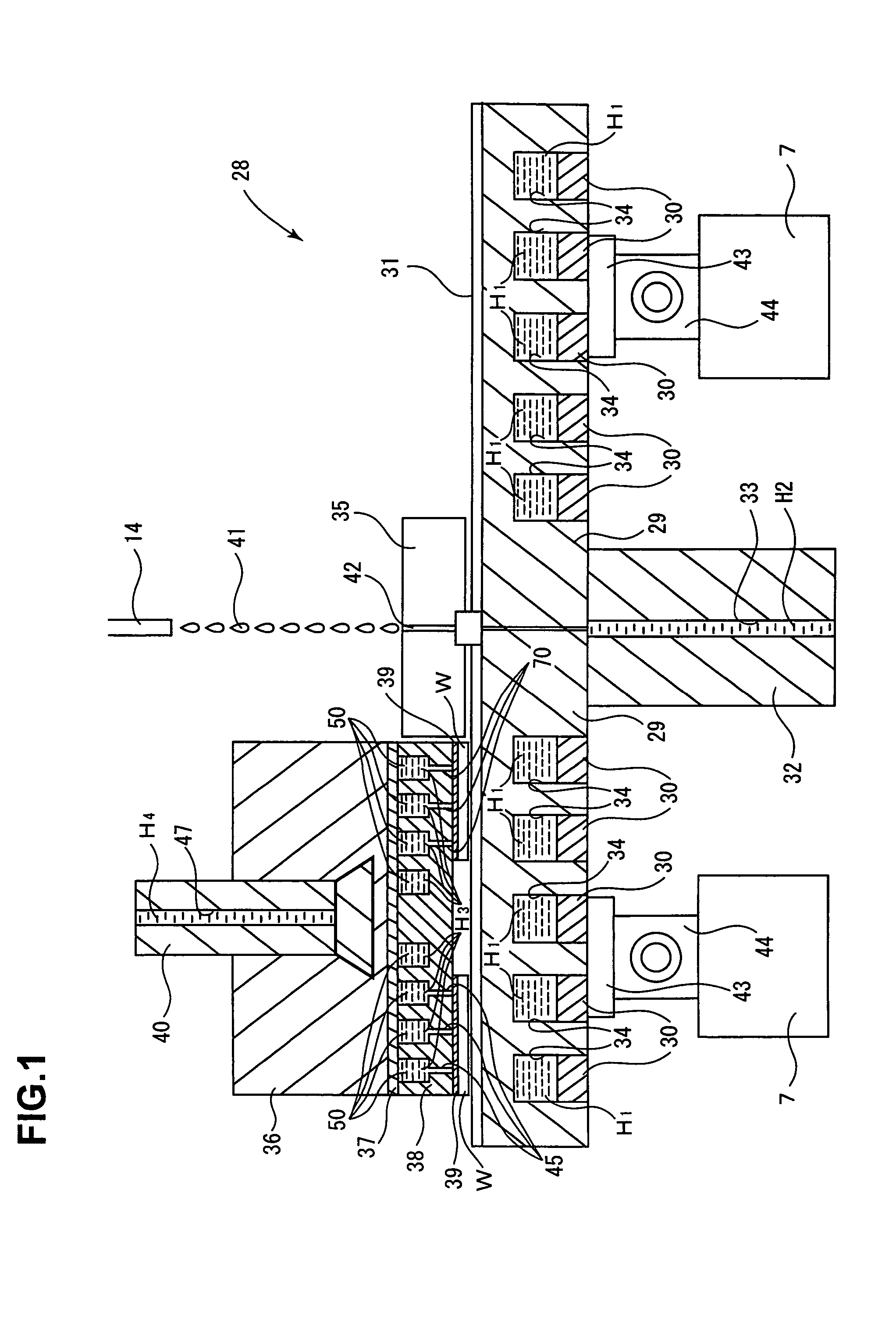
[0123]A batch polishing apparatus having a polishing table and a 4 shaft work holding plate rotation mechanism with a fundamental construction similar to the polishing apparatus shown in FIG. 1 was configured as follows:

[0124]1. Polishing Table: Invar (Shinhokoku Steel Corp., SLE-20A, Fe—Co—Ni—Cr) was used and prepared into a one-piece structure by casting and cooling water flow paths shown in FIGS. 5 and 6 are formed in the structure. Furthermore, as shown in FIG. 5 which depicts part of the flow paths 9 for a temperature adjusting fluid, in such a state as the upper surface portion of the table is partly cutaway, the table was designed such that the flow paths 9 are formed in a meandering manner, a fluid flow in the flow paths 9 are liable, to enter a turbulent state and an average flow rate is increased to raise a heat transfer coefficient to the highest possible level, while portions in which the flow paths 9 are not formed functions as a rib structure 8a to maintain strength of...


PUM

PropertyMeasurementUnit
temperatureaaaaaaaaaa
diameteraaaaaaaaaa

Abstract

There are provided a polishing apparatus and a polishing method capable of performing polishing a work (such as a wafer) with high efficiency and high precision, a novel work holding plate effectively holding a work and an adhering method for a work capable of adhering the work on the work holding plate with high precision. The polishing apparatus comprises: a polishing table(29); and a work holding plate(38), wherein a work held on the work holding plate(38) is polished supplying a polishing agent solution(41) in the apparatus, and in polishing action, an amount of deformation of the polishing table(29) in a direction normal to an upper surface thereof with respect to the upper surface thereof and / or an amount of deformation of the work holding plate(38) in a direction normal to a work holding surface thereof is restricted to 100 m or less by forming the polishing table(29) in one-piece, contriving flow paths of cooling water and others.

Description

[0001]This is a Division of application Ser. No. 09 / 926,243 filed Sep. 28, 2001, now U.S. Pat. No. 6,827,638. The disclosure of the prior application is hereby incorporated by reference herein in its entirety.TECHNICAL FIELD[0002]The present invention relates to a polishing apparatus and a polishing method capable of performing polishing of a work, for example, a silicon wafer (hereinafter may be simply referred to as “wafer”) or the like with high efficiency and high precision, a novel work holding plate for holding a work (for example, a wafer or the like) in a efficient way and a method for adhering a work onto the work holding plate.BACKGROUND ART[0003]Reflecting a tendency to prepare larger diameter silicon wafers and fabricate higher precision devices therewith, requirements for finish precision (thickness uniformity, flatness and smoothness) of a silicon wafer subjected to polishing finish (polished wafer) have been increasingly enhanced.[0004]In order to satisfy such require...

Claims


Application Information

Patent Timeline
Patent Type & Authority Patents(United States)
IPC IPC(8): B24B49/00B24B37/04B24B37/015B24B37/12B24B37/14B24B37/27B24B37/30B24B41/04B24B41/06B24B49/14B24B55/02B24B57/02H01L21/304
CPCB24B37/015B24B37/042B24B37/12B24B37/14B24B37/30B24B41/042B24B41/06B24B49/14B24B55/02B24B57/02
Inventor KIUCHI, ETSUOHAYASHI, TOSHIYUKI
Owner SHIN-ETSU HANDOTAI CO LTD
Why Eureka
Try Eureka