Filter assemblies and systems for intake air for fuel cells
a fuel cell and filter assembly technology, applied in the direction of air cleaner and silencer combination, séparation process, auxillary pretreatment, etc., can solve the problems of fuel cell operation discontinuation, typical compressors producing significant undesirable and annoying noise levels, and affecting the operation of the cell
- Summary
- Abstract
- Description
- Claims
- Application Information
AI Technical Summary
Problems solved by technology
Method used
Image

Examples
first embodiment
[0049] a Filter Assembly
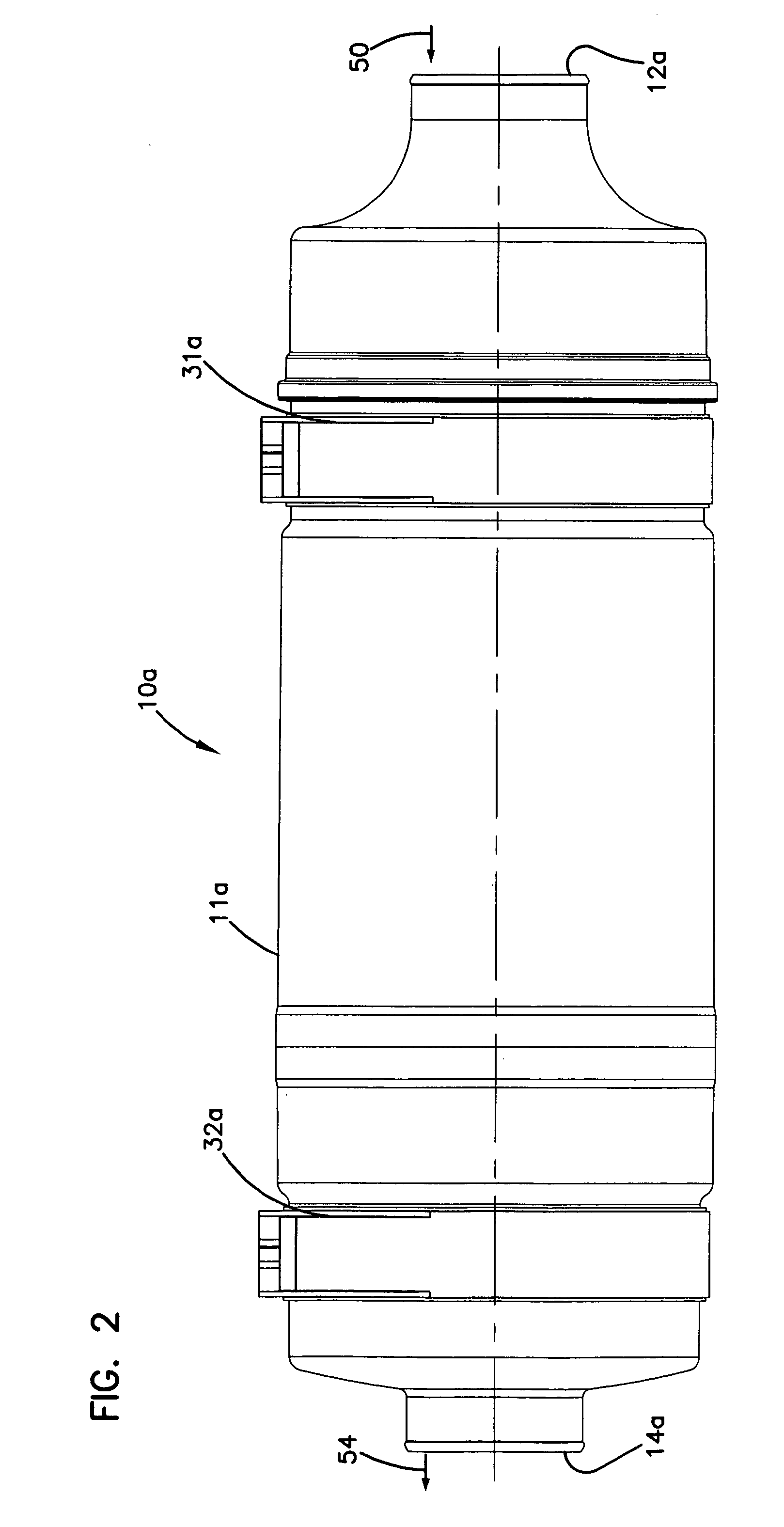
[0050] A first example of a filter assembly configured according to the principles of this invention is shown in FIG. 2. For ease of identification, those elements in the embodiment of FIG. 2 that are the same or which perform the same function as comparable elements previously discussed with respect to the diagrammatic representation of FIG. 1 are followed by an alphabetic designation (i.e., “a”) in FIG. 2. The same will be used when describing further embodiments, such as the embodiment of FIG. 12, wherein the reference numerals are followed by an alphabetic designation (i.e., “b”).
[0051]FIGS. 2 and 3 illustrate a filter assembly 10a for use in a fuel cell operated passenger bus using a stack of PEM fuel cells providing an overall power output of 200 kW. It should be understood that filter assembly 10a is specifically designed for such an application, i.e., a bus running on 200 kW, and that filter assemblies for other applications, such as, for example, ot...
second embodiment
[0082] a filter element for use in the filter assembly of the present invention is illustrated in FIG. 8 as filter element 15b. Filter element 15b is similar to filter element 15a of FIGS. 5 and 7, except that frame 200 of filter element 15b does not include inner annular ring 212.
[0083] Additional details regarding filter element 15a, filter element 15b, and other usable filter elements can be found in U.S. Pat. No. 6,190,432.
[0084] It is understood that other filter constructions, other than those having straight-through flow, can be used. Examples of other particulate filter constructions that can be used include pleated media filters, panel filters, filters having a volume of depth media, and the like.
[0085] A Chemical Removal Portion of the Filter Assembly
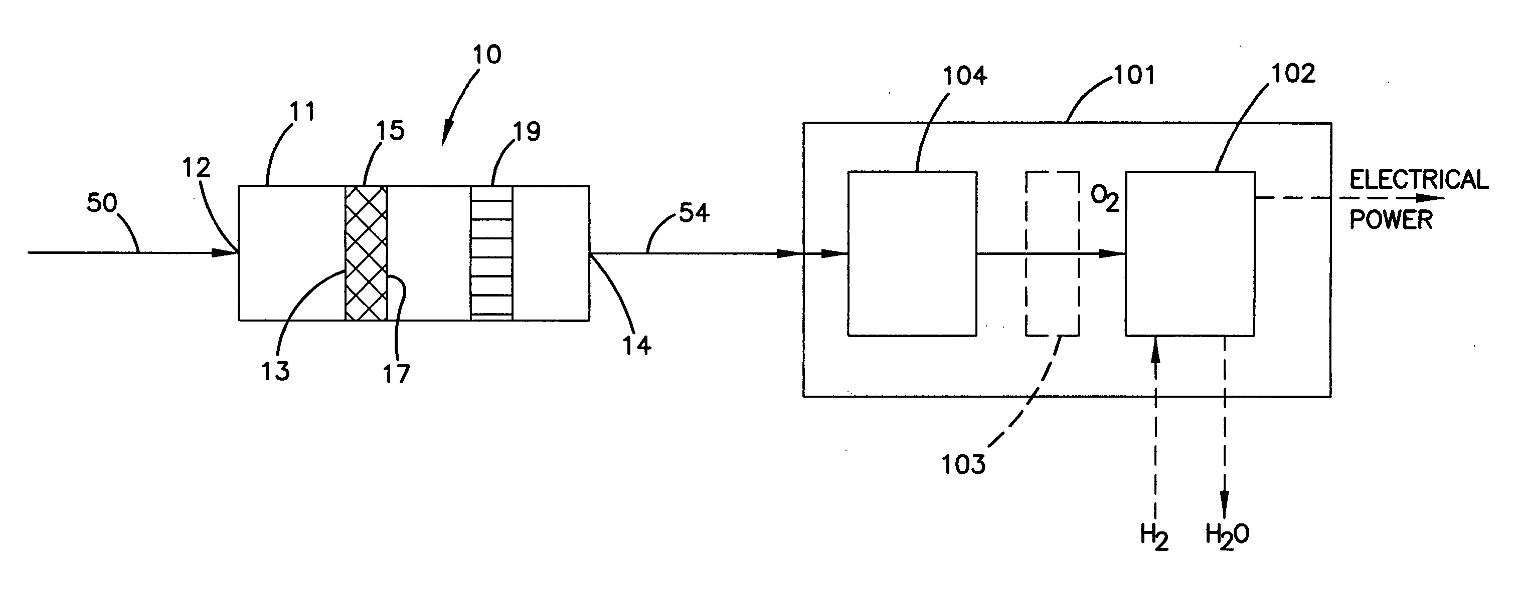
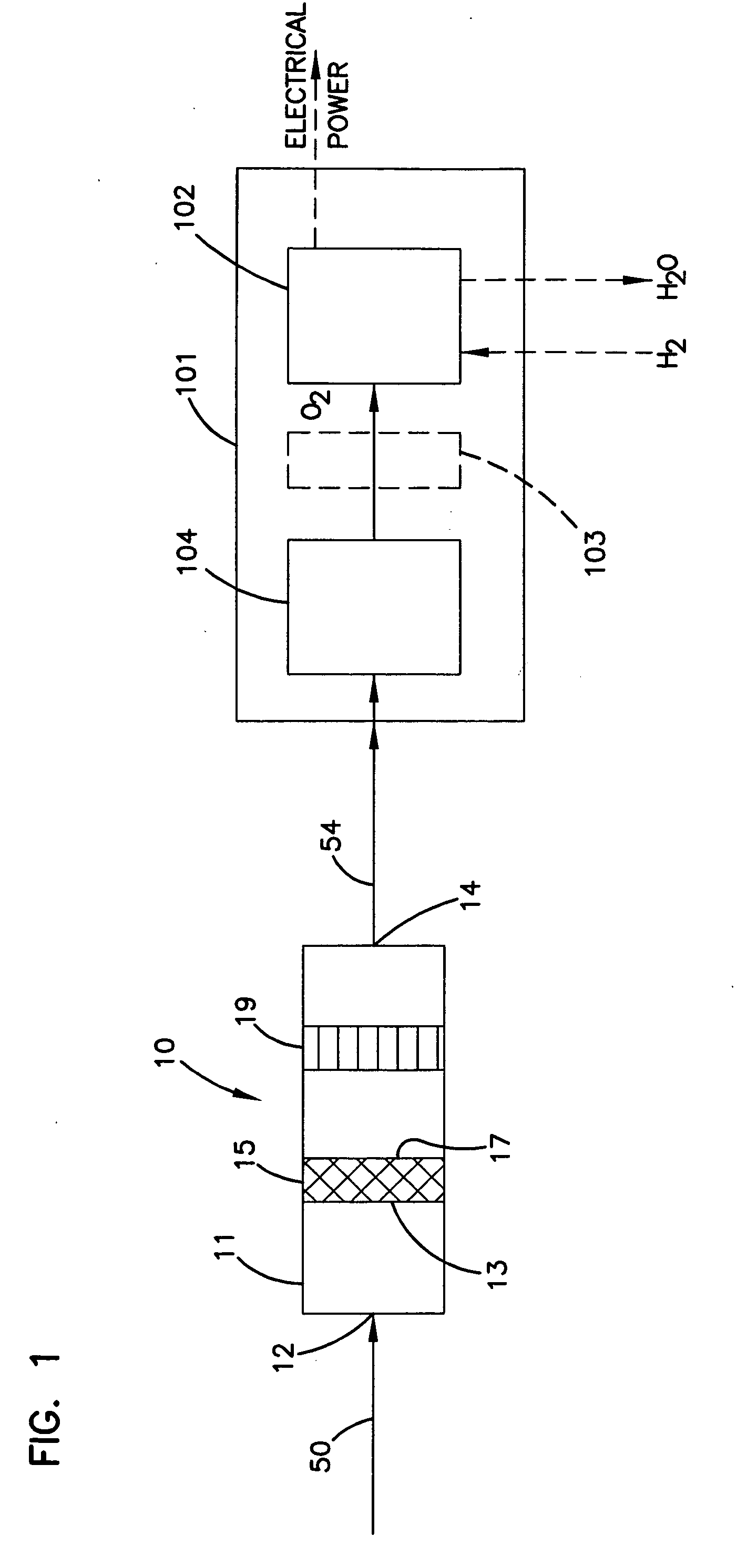
[0086] Referring again to FIG. 1, filter assembly 10 preferably also includes a portion designed to remove contaminants by adsorption, absorption, or both.
[0087] The chemical removal portion typically includes a physisorbe...
third embodiment
[0133] a Filter Assembly
[0134] A third example of a filter assembly is shown in FIGS. 21-23 as a filter assembly 10c. Filter assembly 10c is adapted for use in a fuel cell operated vehicle, such as a passenger car, that uses a stack of PEM fuel cells providing an overall power output of 25 kW. It should be understood that filter assembly 10c is specifically designed for such an application, (i.e., a vehicle running on 25 kW), and that filter assemblies for other applications could be designed for those applications that are different in size, shape and configuration, without departing from the overall features of filter assembly 10c.
[0135] Filter assembly 10c includes a generally cylindrical housing 11c which defines an inlet 12c and an outlet 14c, shown in FIG. 22. Dirty air enters filter assembly 10c via inlet 12c, and clean air exits via outlet 14c. A physical or particulate filter element 415 is positioned within housing 11c. Filter element 415 is generally similar in construct...
PUM
| Property | Measurement | Unit |
|---|---|---|
| frequency | aaaaa | aaaaa |
| frequency | aaaaa | aaaaa |
| frequency distribution | aaaaa | aaaaa |
Abstract
Description
Claims
Application Information
 - R&D
- Intellectual Property
- Life Sciences
- Materials
- Tech Scout
- Unparalleled Data Quality
- Higher Quality Content
- 60% Fewer Hallucinations
Browse by: Latest US Patents, China's latest patents, Technical Efficacy Thesaurus, Application Domain, Technology Topic, Popular Technical Reports.
© 2025 PatSnap. All rights reserved.Legal|Privacy policy|Modern Slavery Act Transparency Statement|Sitemap|About US| Contact US: help@patsnap.com