Support system for power tong assembly

a support system and power tong technology, applied in earthwork drilling and mining, manufacturing tools, construction, etc., can solve the problems of power tong and measurement device not measuring the tru

Inactive Publication Date: 2005-10-27
MCCOY GLOBAL
View PDF12 Cites 8 Cited by
  • Summary
  • Abstract
  • Description
  • Claims
  • Application Information

AI Technical Summary

Benefits of technology

[0012] 2) allow lower portions of the struts to have a degree of lateral and angular freedom of motion when the power tong assembly is suspended for engaging pipe.

Problems solved by technology

However, a drawback of the use of chain-supports of this type is that when the tong assembly is moved aside from the wellhead for storage, as by being deposited on the ground or other support surface, then, in the absence of a lifting force provided by the crane hook, the upper, powered tong is only supported by the post at the back.
This leaves the upper tong supported in a cantilevered manner that may require special reinforcement of the post and post / tong connections or otherwise expose it to damage.
This means that the torque measuring device is not measuring the true torque developed between these two units.

Method used


Image

  • Support system for power tong assembly
  • Support system for power tong assembly
  • Support system for power tong assembly

Examples


Embodiment Construction

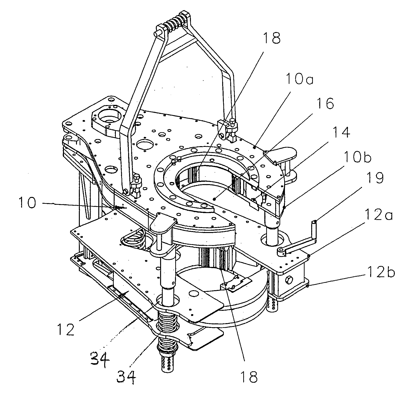
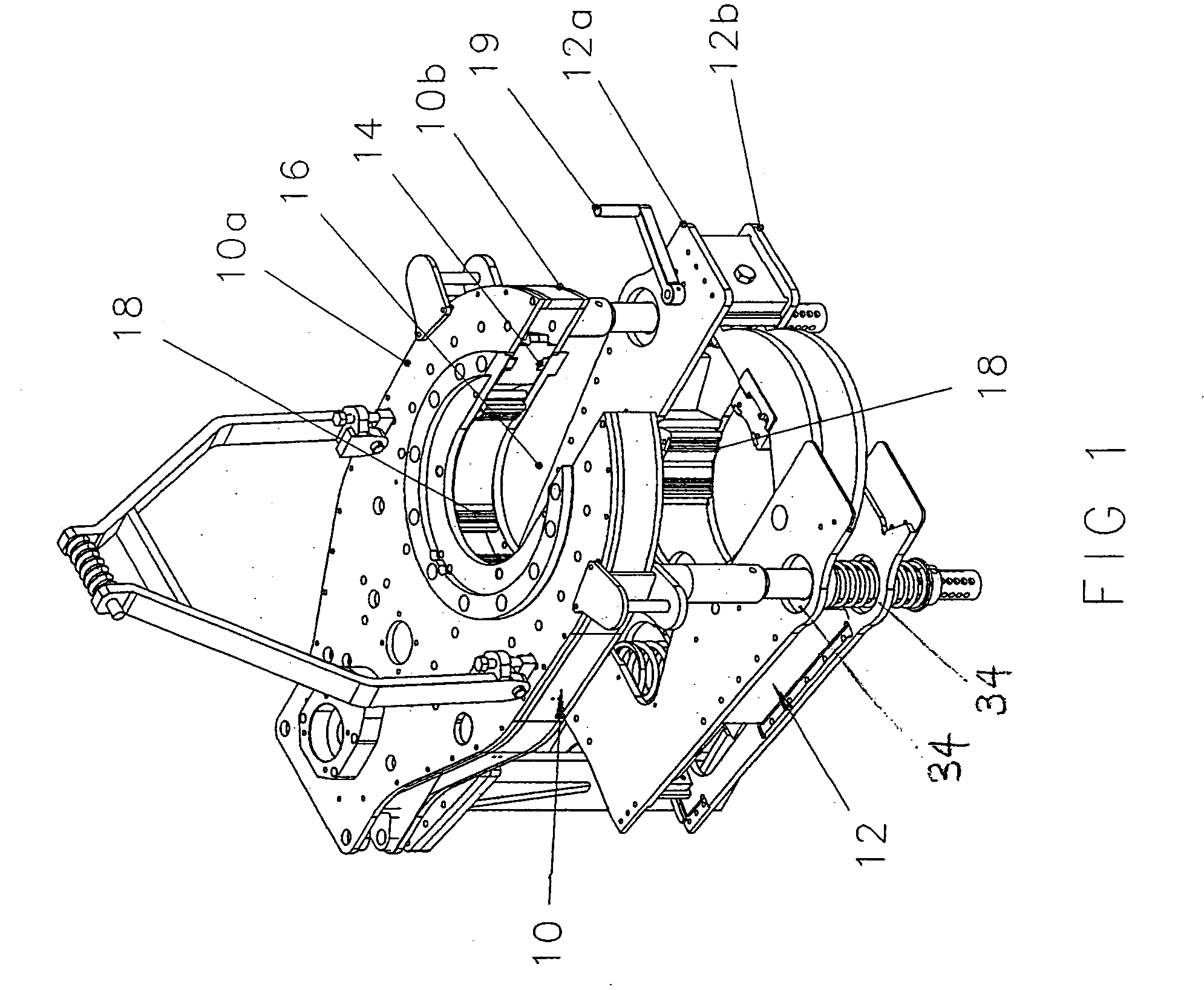
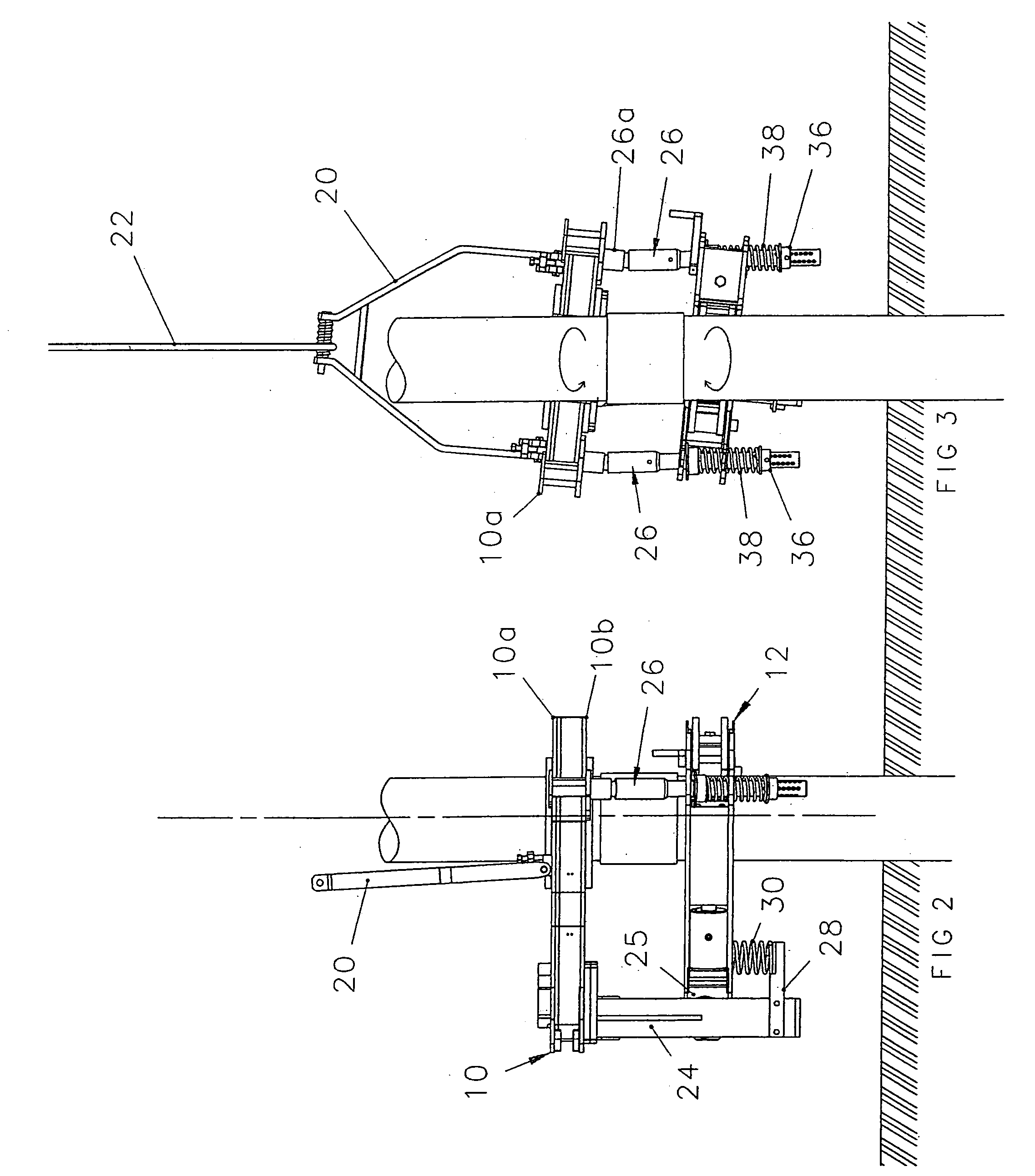
[0039] Referring to FIGS. 1 to 5, the power tong assembly includes an upper powered tong 10 and a lower, backup tong 12. Each tong has upper and lower cage plates, these being plates 10a and 10b for the upper tong, and plates 12a and 12b for the lower tong. The front of each tong has a throat 14 leading to a semi-circular recess 16 for receiving a respective upper and lower pipe section, and each tong has several jaws 18 which are movable radially to grip the pipe sections, operated by cams. The engagement of the jaws on the lower tong are operated by a handle 19. The upper powered tong 10 has, in addition, a hydraulically operated mechanism of a type well-known in the art and which includes a ring gear (not shown) which rotates the jaws to rotate the upper pipe section and thus to effect the coupling and decoupling of pipe joints.

[0040] During use, as shown in FIGS. 2 and 3, the upper tong 10 is held suspended by a bracket 20 fixed to upper cage plate 10a and suspended from cable ...


PUM


Abstract

A tong assembly having a powered tong mounted over a backup tong is supported at its rear by a post with torque measuring means. The powered tong is supported at its front, near its throat, by one or more struts that extend downwardly to the backup tong. Such strut(s) provide support for the powered tong when the assembly is placed on a support surface for storage. The struts each have a joint with a retracted condition in which the joint is rigid when the tong is placed on a support surface, and an extended condition in which the joint allows a degree of lateral displacement when the tong assembly is applying torque to a pipe string. This maximizes the amount of torque passing through the rearward post, and therefore ensures a more accurate sensing of applied torque by the torque-measuring device.

Description

FIELD OF THE INVENTION [0001] This invention relates to power tong assemblies used in the oilfield and elsewhere for the purposes of making and breaking joints between pipe sections. It may also have application to other situations where a torque is to be applied to tubular members and especially where it is desired to provide for a predetermined amount of torque to be applied. BACKGROUND TO THE INVENTION [0002] In using power tongs to make and break joints between sections of a pipe string used in the oil industry, it is customary to provide a tong assembly that includes, generally, an upper powered tong for rotating an upper pipe section of the string, and a lower backup tong which clamps a lower pipe section to resist rotation. Both tongs have jaws which move radially to clamp a pipe section held within a throat portion of the tong, and the powered tong has means, usually hydraulically operated, for rotating its jaws. These two tongs are joined together by suspension means which ...

Claims


Application Information

Patent Timeline
Patent Type & Authority Applications(United States)
IPC IPC(8): B25B13/50E21BE21B19/06E21B19/16
CPCE21B19/166E21B19/164
Inventor DAGENAIS, DANSZALACSI, LESLIE L.FRASER, JONATHAN B.BASLER, HERMANN
Owner MCCOY GLOBAL
Why Eureka
Try Eureka