Vehicle suspension linkage

a technology of suspension linkage and vehicle, which is applied in the direction of resilient suspensions, motorcycles, bicycles, etc., can solve the problems of not being able or practical, unable to achieve smooth pedal stroke, and unable to observe the activation of suspension from pedaling, so as to prevent appreciable suspension activation or pedal feedback, the effect of effective rigidity

Active Publication Date: 2013-02-19
TWERS ERIC RAYMOND
View PDF4 Cites 9 Cited by
  • Summary
  • Abstract
  • Description
  • Claims
  • Application Information

AI Technical Summary

Benefits of technology

[0017]Using FIG. 3 as a reference, a thick line drawing representation of the rearmost member (2), pivotally connected (10) to a trailing arm member (3) itself pivotally connected (11) to the mid point of the vehicle's frame (not shown in this sketch) and also pivotally connected (12) to the second and cross-linked trailing arm member (4) likewise pivotally connected (13) to the vehicle's frame, the path scribed by the axle mounting point (9) protruding below the crossed trailing arm members is shown as the curved line (30). When examining the path scribed by the axle over the range of motion intended for use in the preferred embodiment, as shown by the thick line (15), the path appears to be an arc with a fixed centre at a point (19) above the linkage members. While this approximation of a single pivot suspension operating between the bounds of the dotted lines (35) is acceptable for a general understanding of the effect of the invention through the portion of the path we can see from the bisection of the curve (30) scribed by the axle (9) at regular intervals we demonstrate a shape similar to, if not exactly, that of a logarithmic spiral. The path (30) can be more accurately approximated as a spiral formed from a lengthening radius moving about an also moving pivot point that follows its own logarithmic spiral style path as shown by the composite simulation of an arc (34). This approximation would become more accurate on increasing the frequency with which the path (30) is bisected.
[0018]The invention serves the desired purpose best when the range of motion is limited to the path shown by the thicker line (15). Continuing past the intended range of motion above the shown end point (32), the wheel path loses it's rearward arc as the axle (9) becomes level with the approximation (19) of the location of a virtual single pivot. While the rearward component of the wheel path stops and in fact reverses not far after this end point (32) the approximation of a single pivot suspension continues to have the radius or length of the virtual swing arm continues to increase up until the angle formed between the protrusion the rear most member (2) and the first cross-linked trailing arm member reaches 180°. At this point the lengthening effect collapses. Care must also be taken to configure the lower end point of the wheel path to be above the point at which the path (30) becomes horizontal. Continuing past the intended range of motion below the start point (31) with a configuration where the axle path was in the range of horizontal to becoming vertical again (33) would place the vehicle at rest, without sag in a potential energy well, thus preventing suspension activation unless a very forceful rearward impact was experienced. While this situation could produce an effectively rigid system until subjected to an extreme rearward force, for the purposes of a DH bike this is not desirable. This potential energy well may be explored for systems where this rigid in most circumstances condition would be desirable.
[0019]As a point of interest, the wheel path of this invention is also similar to that of the path scribed by the payload of a trebuchet before launch. This path has shown to be an efficient means of imparting acceleration to a mass, it also shares an intuitively obvious efficiency in absorbing force.
[0020]To temporarily store and dampen the rate of return of the energy absorbed by the suspension linkage a shock absorber and spring unit, consisting of a pneumatic cylinder, elastomer or coil spring combined with a hydraulic or spring property (in the case of an elastomer) based energy damping mechanism will link one or more of the suspension linkages to the frame either directly, through additional linkages or between two of the suspension members. Attaching a shock absorber and spring unit can produce any of linear, rising or falling rates. Since there are benefits and desirable characteristics in each of rising, linear and falling rates as applied to suspension, depending on the ride characteristic sought, selection of shock absorber and spring units may be configured to offer each of these options.
[0021]A pulley mounted to a suspension linkage member in a position such that it will become closer to the drive crank on suspension activation will serve to compensate for the fact that the desired wheel path creates a scenario where the drive chain, otherwise attached, may create undesirable tension induced suspension activation and may transmit suspension activation forces back to the cranks and thus pedals of a chain driven bicycle. The use of such a pulley or drive train mounting point allows the length of the tension portion of a drive chain to remain effectively constant thus preventing appreciable suspension activation or pedal feedback.
[0022]With the tension of the drive chain negated, we can look to beneficial ride effects of driving the rear wheel. Under acceleration, the rear wheel will be driven forward thus serving to extend the suspension and raise the vehicle. Under smooth application of power this will serve to increase ground clearance under pedaling, shorten the wheelbase allowing for easier lifting of the front wheel and allow unbalanced downward forces of uneven pedal strokes to be counteracted by the reciprocal raising of the vehicle's frame under uneven power application.

Problems solved by technology

The inventions of Wronski and Ribi both produce a similar wheel path but introduce certain design issues.
Activation of the suspension from pedaling can also be observed to be induced by the unbalanced momentum of a downward pedal stroke.
While an ideal pedal stroke would provide smooth power to the drive train throughout the entire crank rotation this is not necessarily possible or practical from a standing position and in situations where surface irregularities make a smooth pedal stroke difficult from clearance issues alone.

Method used


Image

  • Vehicle suspension linkage
  • Vehicle suspension linkage
  • Vehicle suspension linkage

Examples


Embodiment Construction

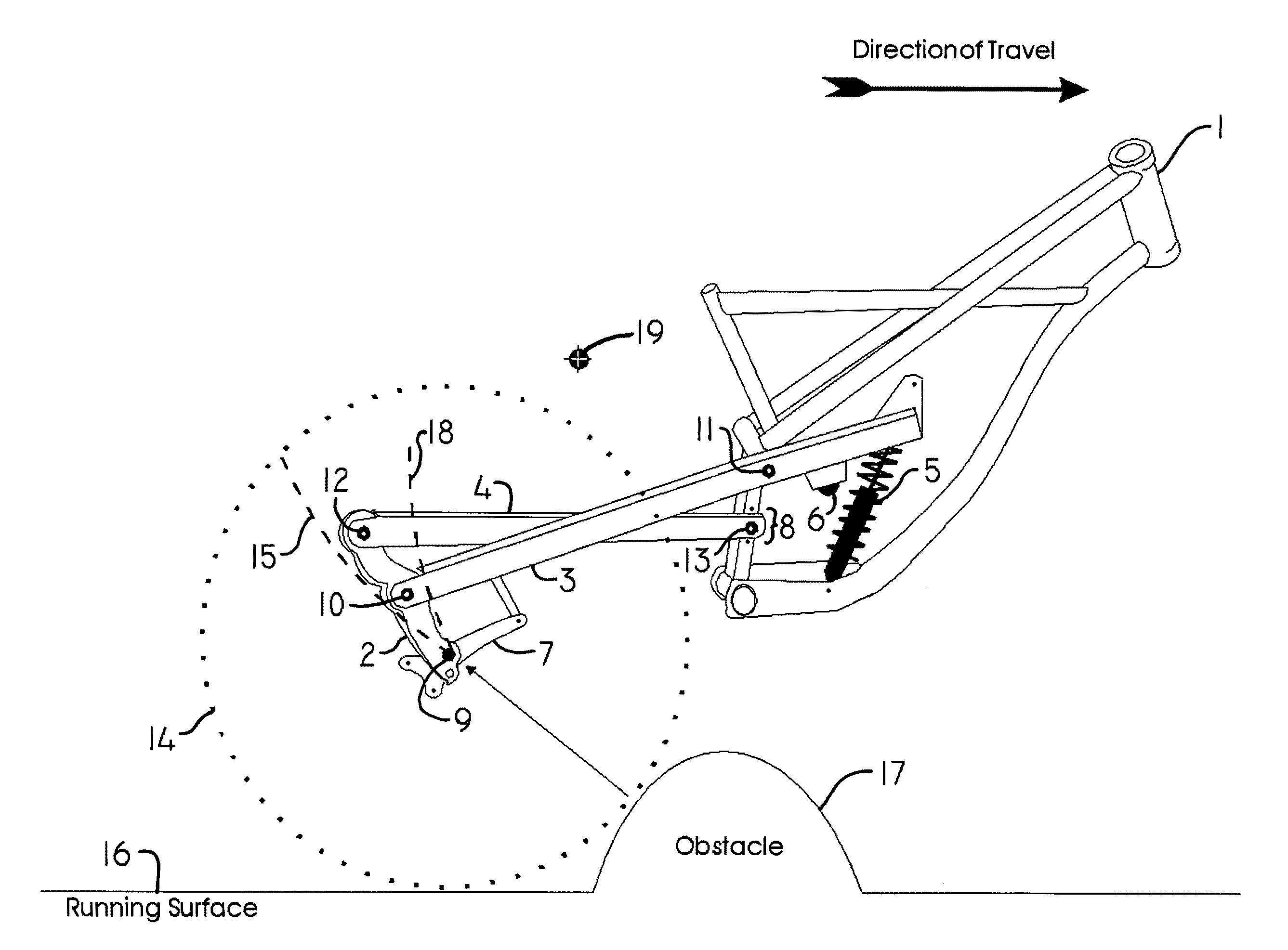
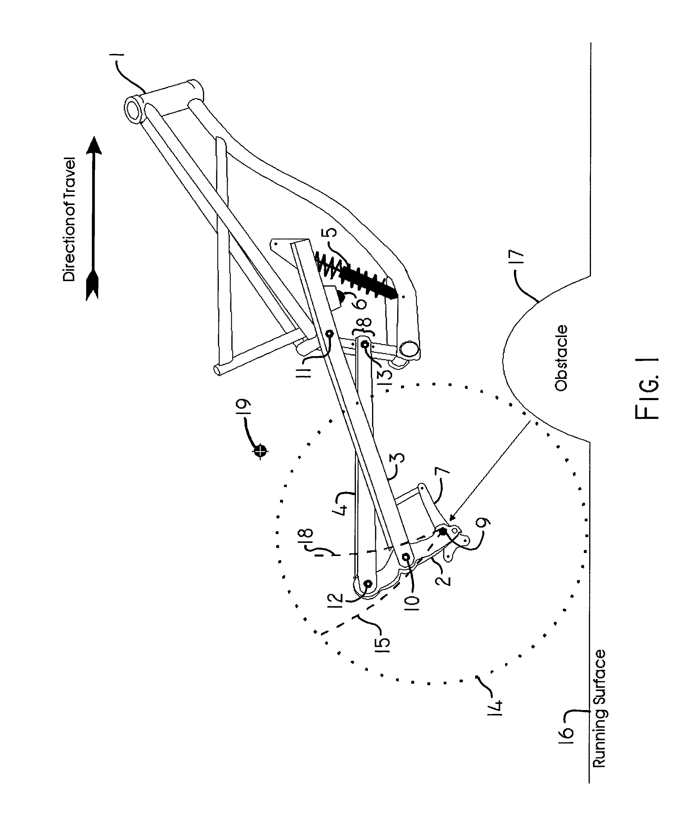
[0068]Referring to FIGS. 1 & 37, I have used the illustration of a bicycle comprising a frame 1 and a rear suspension linkage system comprising a rearmost vertical and slightly rearward member 2 pivotally connected near its mid point 10 to a trailing arm member 3 also pivotally connected 11 near the vertical mid-point of the frame 1, this rearmost member 2 also pivotally connected at its uppermost point 12 to another trailing arm member 4 that crosses the first trailing arm member 3 and pivotally attaches to the frame 1 at a point 13 on the vehicle's frame 1 below the mid point mounted member 3. The rear wheel 14 is attached to the protrusion of the rearmost member 2 at a point 9 below the cross-linked trailing arm members 3&4. A spring and shock absorber unit 5 is connected to store and return absorbed energy in a damped fashion. A tension compensation pulley 6 is present to isolate chain tension forces from the suspension. A brake mechanism 7 is pivotally connected about the axle ...


PUM


Abstract

A suspension linkage that produces a rearward arcing wheel path, comprising of either single or paired pivotally connected members. Cross linked trailing arm members attach pivotally to the frame and a rearmost vertical contact mounting point member with the mounting point for the rear wheel axle, ski or skid protruding below the cross linked trailing arms. This offers benefit for vehicle navigating rough terrain at high speed. The present invention provides a suspension linkage that produces a more rearward arcing wheel path than could be produced by a single pivot placed within the same physical bounds as the pivot points of the invention and introduces desirable ride effects related to accelerating and braking.

Description

[0001]This application is filed in conjunction with Canadian patent application 2,706,678 filed Jun. 8, 2010.BACKGROUND OF THE INVENTION[0002]While much has been done in the prior art to produce a fully suspended bicycle with attention given to isolating pedaling or braking forces from the suspension, the study of wheel path would appear to be focused on isolating these forces. For many implementations of the fully suspended bicycle, pedaling efficiency is of utmost concern. For what is known as a down hill mountain bicycle, or DH Bike, maintaining speed and control over extreme irregularities in the running surface is often the primary concern.[0003]A DH Bike is almost always ridden in a standing position using gravity as the primary force for acceleration. Pedaling becomes a secondary method of maintaining the bicycle's velocity over rough terrain or to add additional acceleration when the terrain is not steep enough.[0004]After several years of studying the prior art as a rider a...

Claims


Application Information

Patent Timeline
Patent Type & Authority Patents(United States)
IPC IPC(8): B62K3/00
CPCB62K25/26B62K25/28B62K25/286
Inventor TWERS, ERIC RAYMOND
Owner TWERS ERIC RAYMOND
Why Eureka
Try Eureka