Method and apparatus for generating an orthorectified tile

a technology of orthorectification and tile, applied in the field of method for generating an orthorectification tile, can solve the problems of inaccurate geo-position data, high cost of aerial or satellite photography, inaccurate determination of the position of the sign post, etc., and achieve the effect of accurately determining the position and determining the position

Active Publication Date: 2014-09-30
TOMTOM GLOBAL CONTENT
View PDF11 Cites 11 Cited by
  • Summary
  • Abstract
  • Description
  • Claims
  • Application Information

AI Technical Summary

Benefits of technology

[0017]The invention is based on the recognition that a mobile mapping vehicle which drives on the surface of the earth, records surface collected geo-position image sequences with terrestrial based cameras. Some of said image sequences include the road in front of the vehicle. Generally, the driving direction of the vehicle is substantially parallel to the surface of the road in front of the vehicle. Furthermore, the position and orientation of the camera with respect to the vehicle and thus with respect to the road surface is known. The position and orientation of the vehicle is determined by means of a GPS receiver and inertial measuring device, such as a gyroscope. All the position and orientation information enables us to convert by means of trigonometry the source images into an orthorectified tile representing a view that accurately approximates an orthorectified view. An orthorectified view according to the invention corresponds to a view from above with a looking axis which is perpendicular to a predefined plane or surface. The orthorectified tile is an image in which every point in the image is as if it is being viewed from directly above.
[0049]This aspect of the invention enables us retrieve from one data source both horizontal information and vertical information. For both type of information there is one source image which comprises them at least partially. This image makes it possible to determine accurately the geo-position of horizontal information as well as the vertical information. Vertical information, e.g. a sign post, is normally visible in one image, whereas horizontal information, e.g. the lanes before a crossing, extends over several images. Therefore, pixels and position and orientation information from more then one source image could be needed to obtain the accurate position of horizontal information. The accurate geo-position of the horizontal and vertical information enables to construct accurately a perspective image that has both vertical data, such as road signs, and horizontal data, such as center lines, all together having the same reference plane for their respective position data. Only one data source is used to determine both the horizontal data and the vertical data. As all data is extracted from one data source, a very accurate relative position measurements can be obtained. Furthermore, the cost to extract the vertical and horizontal data are low compared to the cost to extract horizontal data from aerial images and vertical data from terrestrial based images.

Problems solved by technology

To obtain such images with aerial or satellite photography is very expensive and there is no guarantee that all the road horizontal information is captured.
However, errors are often introduced, which can result in inaccurate mapping of the geo-position data.
The main problem is that normally aerial images are not taken exactly perpendicular to the surface of the earth.
The lack of accurate height information of objects in an aerial image, in combination with the triangulation process used to determine the orthorectified image, can result in an inaccuracy of such images up to a dozen of meters.
But still, there is a limit to the accuracy obtained vs. the cost.
Vertical road information cannot be obtained from typical lookdown aerial or satellite images.
However, the determined geo-positions corresponding to horizontal data obtained from aerial images do not always match the determined geo-positions corresponding to vertical data obtained from mobile data images.
This can result in the incorrect placement or interpretation of data if information from both data sources are to be integrated into the same digital map database.
Additionally, this will result in confusing situations if both horizontal and vertical data are displayed simultaneously in a navigation system or the like.
Furthermore, the use of two types of data sources influences the production costs of a digital map database negatively.

Method used


Image

  • Method and apparatus for generating an orthorectified tile
  • Method and apparatus for generating an orthorectified tile
  • Method and apparatus for generating an orthorectified tile

Examples


Embodiment Construction

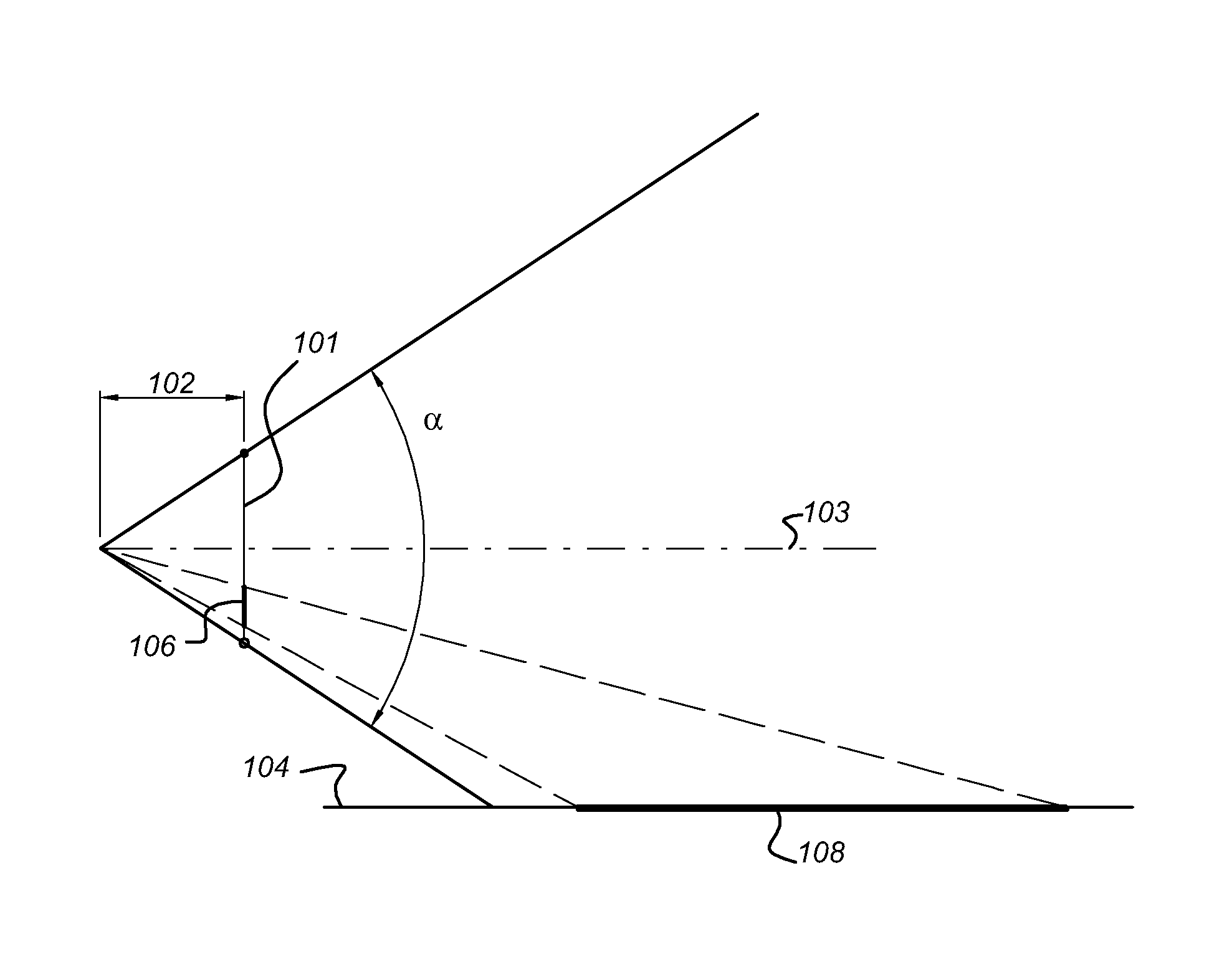
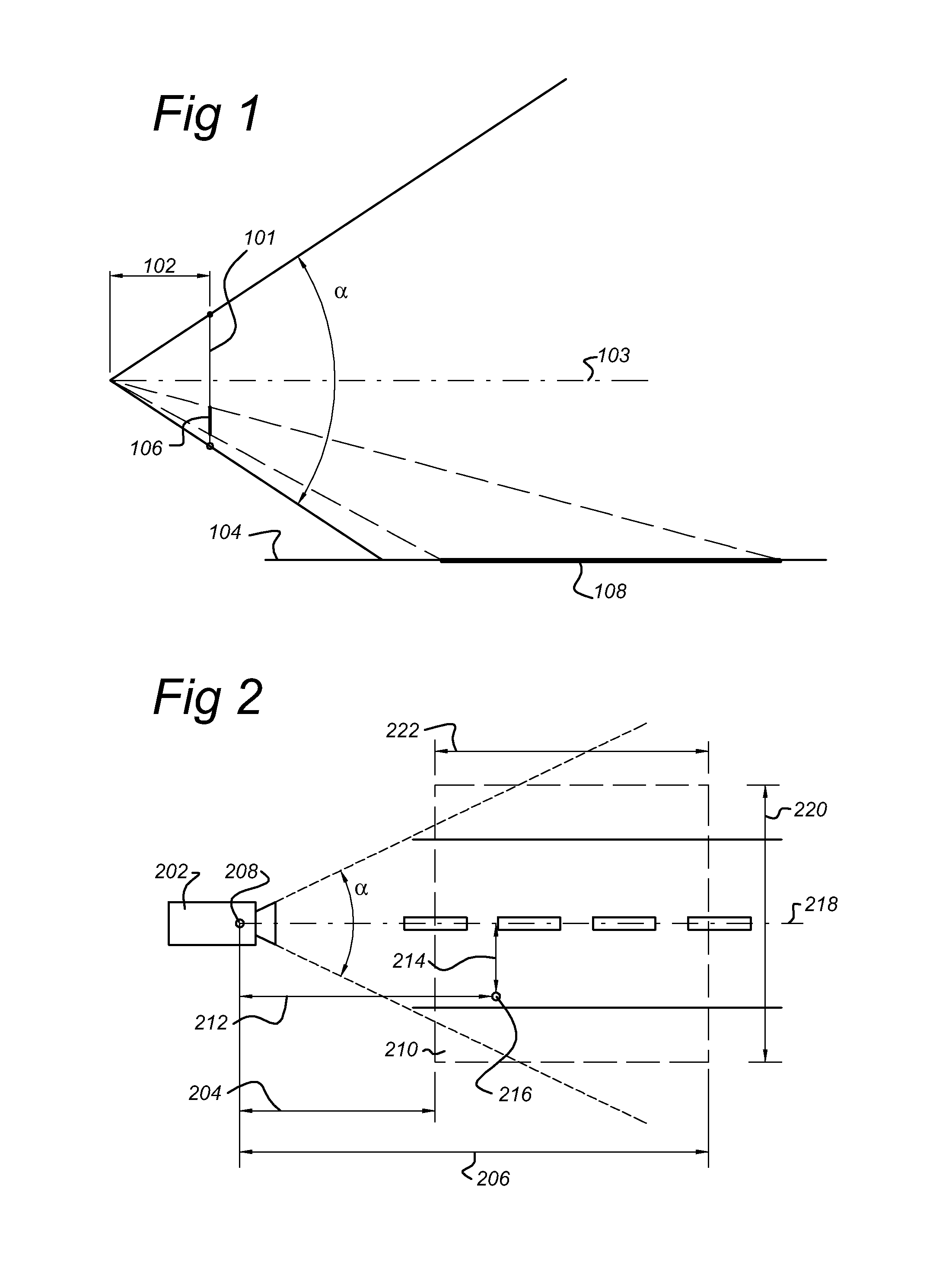
[0075]FIG. 1 shows a side view of the general principle of conversion of source images into orthorectified tiles. An image sensor 101 in a camera or CCD-camera 202 (shown in FIG. 2) records a sequence of source images. The source images represent more or less vertical images which are recorded by a terrestrial based camera. The source images could be a sequence of still pictures recorded by means of a still picture camera, which camera is triggered every displacement of e.g. 10 meter. A camera comprising the image sensor has an angle of view α. The angle of view α is determined by the focal length 102 of the lenses of the camera. The angle of view α could be in the range of 45°103, which is in the centre of the angle of view. In FIG. 1, the looking axis 103 is parallel to a horizontal plane 104. The image sensor 101 is mounted perpendicular to the looking axis 103. In this case, the image sensor 101 records “pure” vertical source images. If further the height of the image sensor is ...


PUM


Abstract

A method is disclosed for generating an orthorectified tile. In at least one embodiment, the method includes retrieving source images obtained by way of a terrestrial based camera; retrieving position data associated with the source images; retrieving orientation data associated with the source images; and converting source image by means of corresponding position data and orientation data to obtain the orthorectified tile. Orthorectified tiles are used to generate an orthorectified mosaic. As such, images recorded by terrestrial based camera may be used to generate a map of a road surface with corresponding road signs.

Description

FIELD OF THE INVENTION[0001]The present invention relates to a method for generating an orthorectified tile. The invention further relates to a processor readable storage medium carrying an orthorectified tile, a computer arrangement for generating an orthorectified tile. Furthermore, the invention relates to a method of collecting both positionally accurate horizontal information and positionally accurate vertical information from source images of at least one terrestrial based image sequence captured by a terrestrial based camera and a method of collecting both positionally accurate horizontal information and positionally accurate object information from at least one source image obtained by a terrestrial based camera, wherein the object is visibly attached to the groundPRIOR ART[0002]There is a need to collect a large number of horizontal road information e.g. lane dividers, road centrelines etc. for digital map databases used in navigation systems and the like. This information ...

Claims


Application Information

Patent Timeline
Patent Type & Authority Patents(United States)
IPC IPC(8): G09G5/00G06T3/00G06T3/40G06T5/00G09B29/10G11C11/02
CPCG06T3/00G09B29/102G11C11/02G01C21/32G06T5/006G06T3/4038G01C11/02G01C21/3881G01C21/3848G01C21/3822
Inventor KMIECIK, MARCIN MICHALNOWAK, WOJCIECH TOMASZ
Owner TOMTOM GLOBAL CONTENT
Why Eureka
Try Eureka