
System and method for monitoring a state of a fluid in an indoor space as well as a climate control system

a monitoring system and indoor space technology, applied in the direction of instruments, heat measurement, electrical apparatus construction details, etc., can solve the problems of high cost of sensors used to gather raw data, complicated measurement of flow field, and high cost of air velocity, so as to achieve the effect of cheaper sensors

Active Publication Date: 2017-02-16
NEDERLANDSE ORG VOOR TOEGEPAST-NATUURWETENSCHAPPELIJK ONDERZOEK (TNO)
View PDF2 Cites 10 Cited by
  • Summary
  • Abstract
  • Description
  • Claims
  • Application Information

AI Technical Summary

Benefits of technology

The invention provides a method and system for using cheaper sensors to estimate the flow field in an indoor space. This is achieved by reconstructing the flow field from temperature measurements using a Kalman-based approach. The approach accurately approximates the non-linear flow field by discretized linear versions, without introducing a significant amount of noise. The system includes a data processor to verify if the difference between the temperature field and the predicted temperature field complies with a predetermined requirement and update the estimated state of the fluid accordingly. The iterative process allows for a relatively detailed and accurate assessment of the flow field, with minimal computational complexity. Overall, the invention provides a cost-effective solution for estimating the flow field in indoor spaces.

Problems solved by technology

In particular measurement of the flow field is complicated.
However, as air velocities in an indoor space typically are low, only two principles are appropriate to achieve this.
The known methods have the disadvantage that the sensors that are used to gather the raw data are expensive, and therewith inattractive for use, in particular in large indoor spaces.
Generally, in indoor climate control, e.g. in greenhouses, this is not the case and more complicated simulation models are necessary.
This also implies that the results obtained indirectly from the measurements are more susceptible for noise.

Method used


Image

  • System and method for monitoring a state of a fluid in an indoor space as well as a climate control system
  • System and method for monitoring a state of a fluid in an indoor space as well as a climate control system
  • System and method for monitoring a state of a fluid in an indoor space as well as a climate control system

Examples


Embodiment Construction

[0110]Like reference symbols in the various drawings indicate like elements unless otherwise indicated.

[0111]In the following detailed description numerous specific details are set forth in order to provide a thorough understanding of the present invention. However, it will be understood by one skilled in the art that the present invention may be practiced without these specific details. In other instances, well known methods, procedures, and components have not been described in detail so as not to obscure aspects of the present invention.

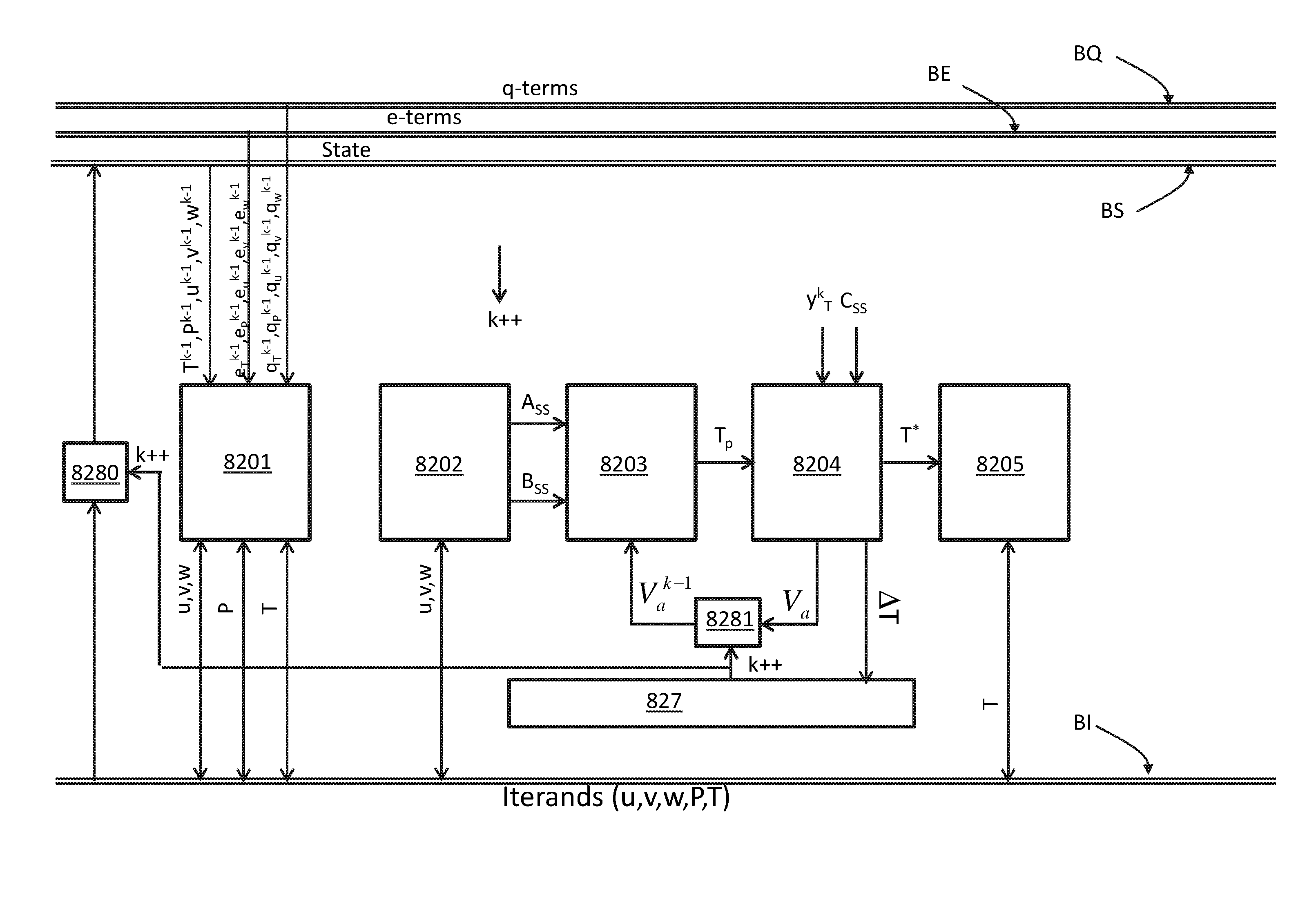
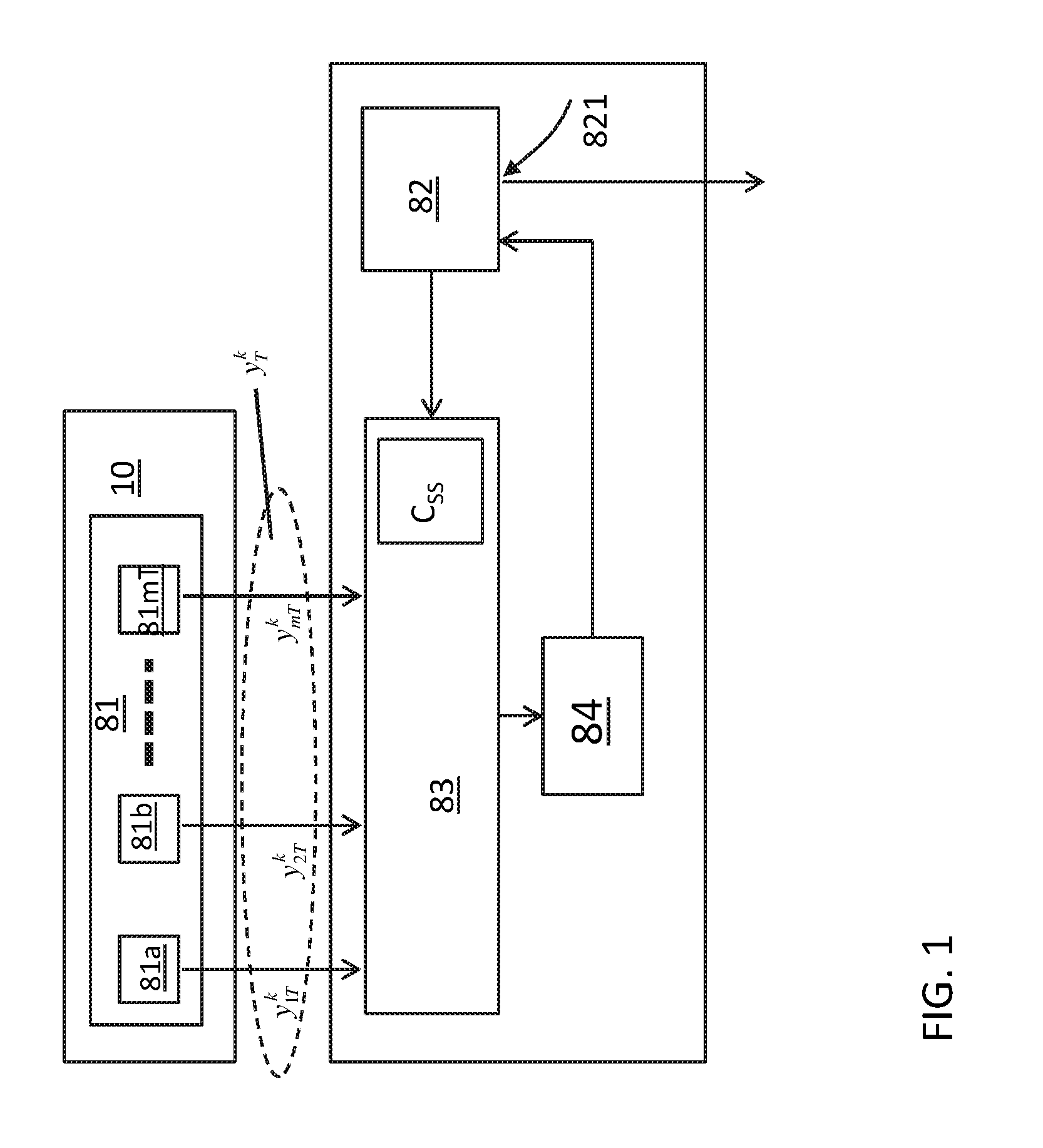
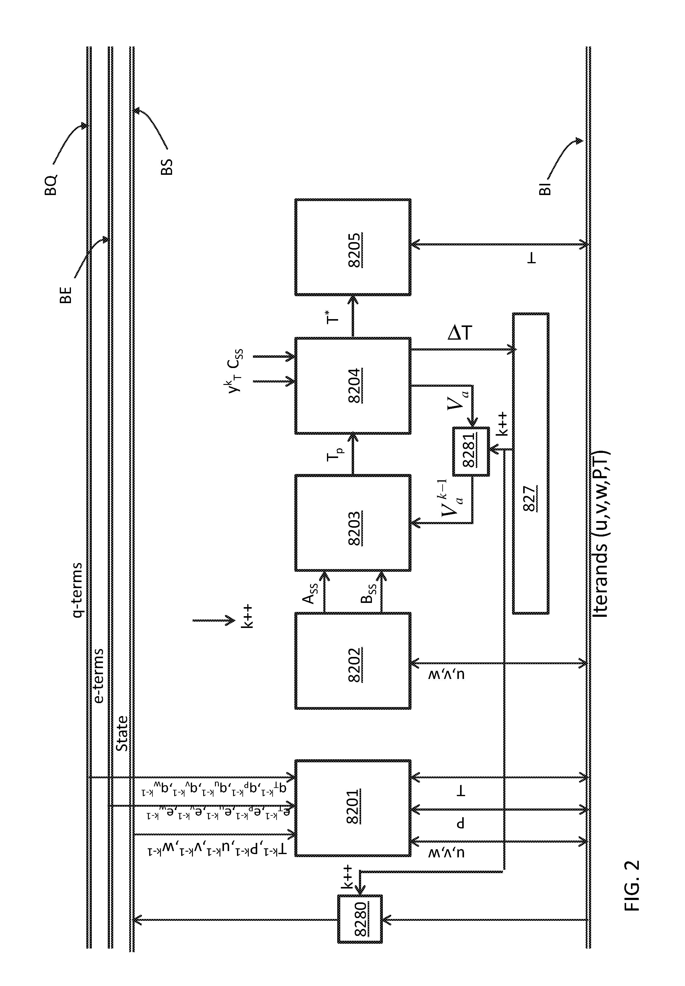
[0112]FIG. 1 schematically shows a system according to the first aspect for monitoring a state of a fluid in an indoor space 10 including a state of a flow field for said fluid. The system includes an input unit 81 with a plurality of temperature sensors 81a, 81b, . . . , 81mT to provide respective temperature measurement data y1Tk, y2Tk, . . . , ymTk indicative for a temperature field in said indoor space 10 at a point in time k. The temperature ...


PUM

PropertyMeasurementUnit
temperatureaaaaaaaaaa
temperature fieldaaaaaaaaaa
pressureaaaaaaaaaa

Abstract

A monitoring system for monitoring a state of a fluid in an indoor space including a state of a flow field for said fluid is presented. The system includes an input unit (81), a simulation unit (82), a comparison unit (83) and a state correction unit (84). The input unit (81) comprises a plurality of temperature sensors (81a, 81b, . . . , 81mT) to obtain temperature measurement data indicative for a temperature field in said indoor space. The simulation unit (82) is provided to simulate the fluid in said indoor space according to an indoor climate model to predict a state of the fluid including at least a temperature field and a flow field for the fluid in said indoor space, and has an output to provide a signal indicative for the flow field. The comparison unit (83) is provided to compare the predicted temperature field with the temperature measurement data, and the state correction unit (84) is provided to correct the predicted state of the fluid based on a comparison result of said comparison unit (83). The monitoring system may be part of a climate control system.

Description

BACKGROUND OF THE INVENTION[0001]Field of the Invention[0002]The present invention relates to a monitoring system for monitoring a state of a fluid in an indoor space.[0003]The present invention further relates to a method for monitoring a state of a fluid in an indoor space.[0004]The present invention further relates to a climate control system including the monitoring system.[0005]The present invention further relates to a climate control method including the monitoring method.[0006]Related Art[0007]In particular in indoor climate control systems it is desired to determine the actual state of the indoor climate, i.e. the state of a fluid, in an indoor space, such as a greenhouse. The state of the fluid may comprise a temperature field of the fluid, a flow field of the fluid, and a humidity field. In particular measurement of the flow field is complicated.[0008]According to a known approaches a smoke source is placed in the indoor space and it is optically determined how the smoke ...

Claims


Application Information

Patent Timeline
Patent Type & Authority Applications(United States)
IPC IPC(8): G01P5/00G01K7/42G01P5/10
CPCG01P5/001G01K7/427G01P5/10H05K7/20836
Inventor BOOIJ, PAUL SEBASTIANFRANSMAN, JEROEN EDWINSIJS, JORIS
Owner NEDERLANDSE ORG VOOR TOEGEPAST-NATUURWETENSCHAPPELIJK ONDERZOEK (TNO)
Learn More