Eureka AIR delivers breakthrough ideas for toughest innovation challenges, trusted by R&D personnel around the world.

Circuit breaker-like apparatus with combination current transformer

a circuit breaker and transformer technology, applied in the direction of transformer/inductance, transformer/inductance, magnetic core, etc., can solve the problems of affecting the protection effect of existing mcps for both relatively low current level and relatively high current level, and affecting the effect of current sensed range, reducing the amount of remnant flux or saturation

Active Publication Date: 2008-01-17
SCHNEIDER ELECTRIC USA INC
View PDF40 Cites 9 Cited by
  • Summary
  • Abstract
  • Description
  • Claims
  • Application Information

AI Technical Summary

Benefits of technology

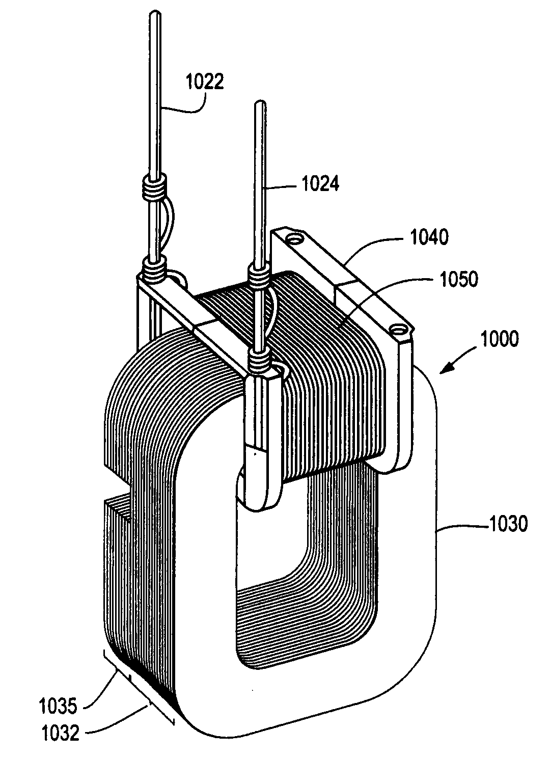
[0007]Briefly, according to an embodiment of the present invention, a current transformer that extends the range of a circuit breaker, such as a motor circuit protector, includes both solid and gapped laminations that are staked and stacked together to form a single core. The solid laminations produce secondary current sufficient to power electronic components of the circuit breaker and sense relatively low currents. The gapped laminations produce secondary current sufficient to power the electronic components and sense relatively high currents, thereby extending the range of sensed currents for the MCP. The gapped laminations decrease the amount of remnant flux or saturation in the current transformer compared to solid cores.
[0008]The number of solid laminations and gapped laminations as well as the size of the gap in the gapped laminations are selected to fault power the MCP electronic components and sense a range of currents corresponding to locked-rotor or in-rush motor currents as well as high instantaneous short-circuit currents. As the number of solid laminations are increased, the saturation knee threshold region of the core's transfer function is pushed higher, resulting in saturation at a higher peak current. Gapped laminations are added for higher current sensing based on remnant flux requirements. As each gapped lamination is added, the core's saturation region shifts to a higher peak current value. By adjusting the ratio of solid-to-gapped laminations, a variety of operating ranges can be achieved for the MCP, operating ranges that can be significantly extended compared to existing MCPs. Moreover, the linear region of the current transformer can be extended by increasing the ratio of solid-to-gapped laminations and / or by varying the number of turns wound on the primary coil of the current transformer, resulting in more accurate approximation of the primary current. In a specific implementation, the core includes sixteen solid laminations and eight gapped laminations, resulting in a current transformer that can sense locked-rotor currents in the range of 10 A as well as high fault currents in the range of 3000 A.

Problems solved by technology

A circuit breaker may be tripped by an overload or short circuit, which causes an interruption of power to the load.
MCPs that sense relatively low currents may not be suitable for motors having a relatively low in-rush current because tripping will occur during normal operation of the motor.
Because of their limited operating range, some existing MCPs cannot protect for both relatively low current levels and relatively high current levels.
Other existing MCPs that can protect against a wider range of fault currents are very large and their current transformers require large volumes of steel to remain in their linear range of operation.
Presently, current transformers used in existing circuit breaker devices are designed to supply power to trip unit electronics, or to sense low current ranges, or to sense high current ranges, and have a limited operating range.
Thus, current transformer devices designed to sense low fault currents cannot effectively sense high fault currents.
An additional current transformer specifically designed for supplying power to the trip unit electronics must be incorporated into the circuit breaker, increasing its size, complexity, and cost.
Similarly, current transformer devices designed to sense high fault currents cannot effectively sense low fault currents.

Method used


Image

  • Circuit breaker-like apparatus with combination current transformer
  • Circuit breaker-like apparatus with combination current transformer
  • Circuit breaker-like apparatus with combination current transformer

Examples


Embodiment Construction

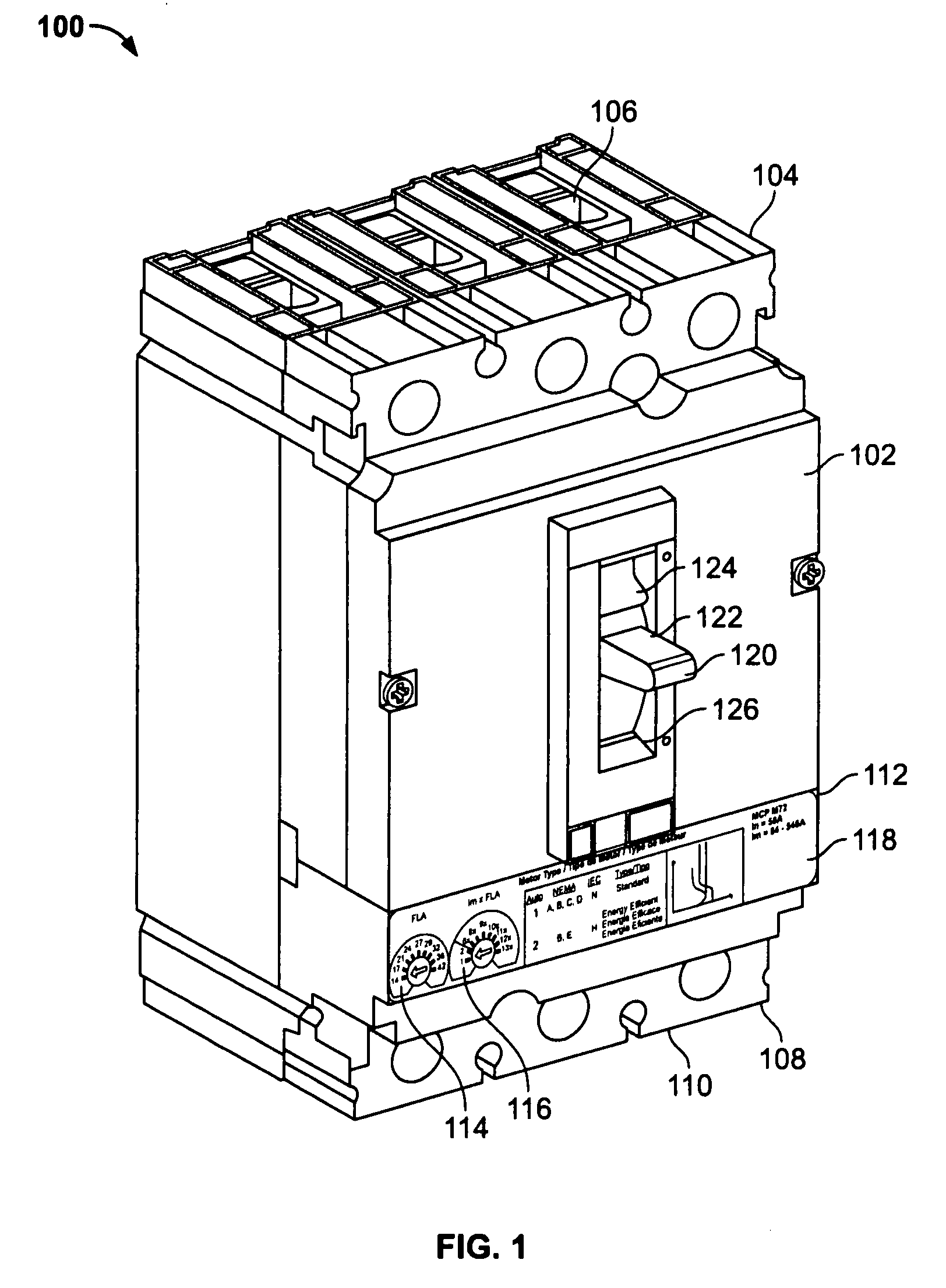
[0022]Turning now to FIG. 1, an electronic motor circuit protector 100 is shown. The motor circuit protector 100 includes a durable housing 102 including a line end 104 having line terminals 106 and a load end 108 having load lugs or terminals 110. The line terminals 106 allow the motor circuit protector 100 to be coupled to a power source and the load terminals 110 allow the motor circuit protector 100 to be coupled to an electrical load such as a motor as part of a motor control center (“MCC”). In this example the motor circuit protector 100 includes a three-phase circuit breaker with three poles, although the concepts described below may be used with circuit protectors with different numbers of poles, including a single pole.

[0023]The motor circuit protector 100 includes a control panel 112 with a full load ampere (“FLA”) dial 114 and an instantaneous trip point (“Im”) dial 116 which allows the user to configure the motor circuit protector 100 for a particular type of motor to be...


PUM


Abstract

In a circuit breaker, a current transformer for fault powering trip unit electronics and sensing low currents and high currents includes a core with solid laminations and gapped laminations to sense a wide range of currents from locked-rotor currents to high, instantaneous short-circuit currents in a single current transformer. The current transformer can also fault power trip unit electronics without requiring an additional current transformer. The operating range of the circuit breaker is significantly enhanced compared to existing breakers that can sense only a limited range of current levels.

Description

CROSS-REFERENCE TO RELATED APPLICATION[0001]This application claims the benefit of U.S. Provisional Application No. 60 / 831,006, filed Jul. 14, 2006, entitled “Motor Circuit Protector,” which is hereby incorporated by reference in its entirety.FIELD OF THE INVENTION[0002]This invention relates to current transformer devices used for circuit breakers, motor control units, or the like, and more particularly, to current transformers for powering and sensing current over broad current ranges.BACKGROUND OF THE INVENTION[0003]As is well known, a circuit breaker is an automatically operated electro-mechanical device designed to protect a load from damage caused by an overload or a short circuit. A circuit breaker may be tripped by an overload or short circuit, which causes an interruption of power to the load. A circuit breaker can be reset (either manually or automatically) to resume current flow to the load. One application of circuit breakers is to protect motors as part of a motor contr...

Claims


Application Information

Patent Timeline
IPC IPC(8): H01F27/24
CPCH01F3/02H01F3/14H01F38/30H01F27/306H01F27/02
Inventor COLSCH, SUSAN JEAN WALKERDUNNE, DAVID JOSEPHMALO, KEVIN JOHNSTUDER, RICHARD ALLEN
Owner SCHNEIDER ELECTRIC USA INC
Why Eureka
Eureka Blog
Learn More