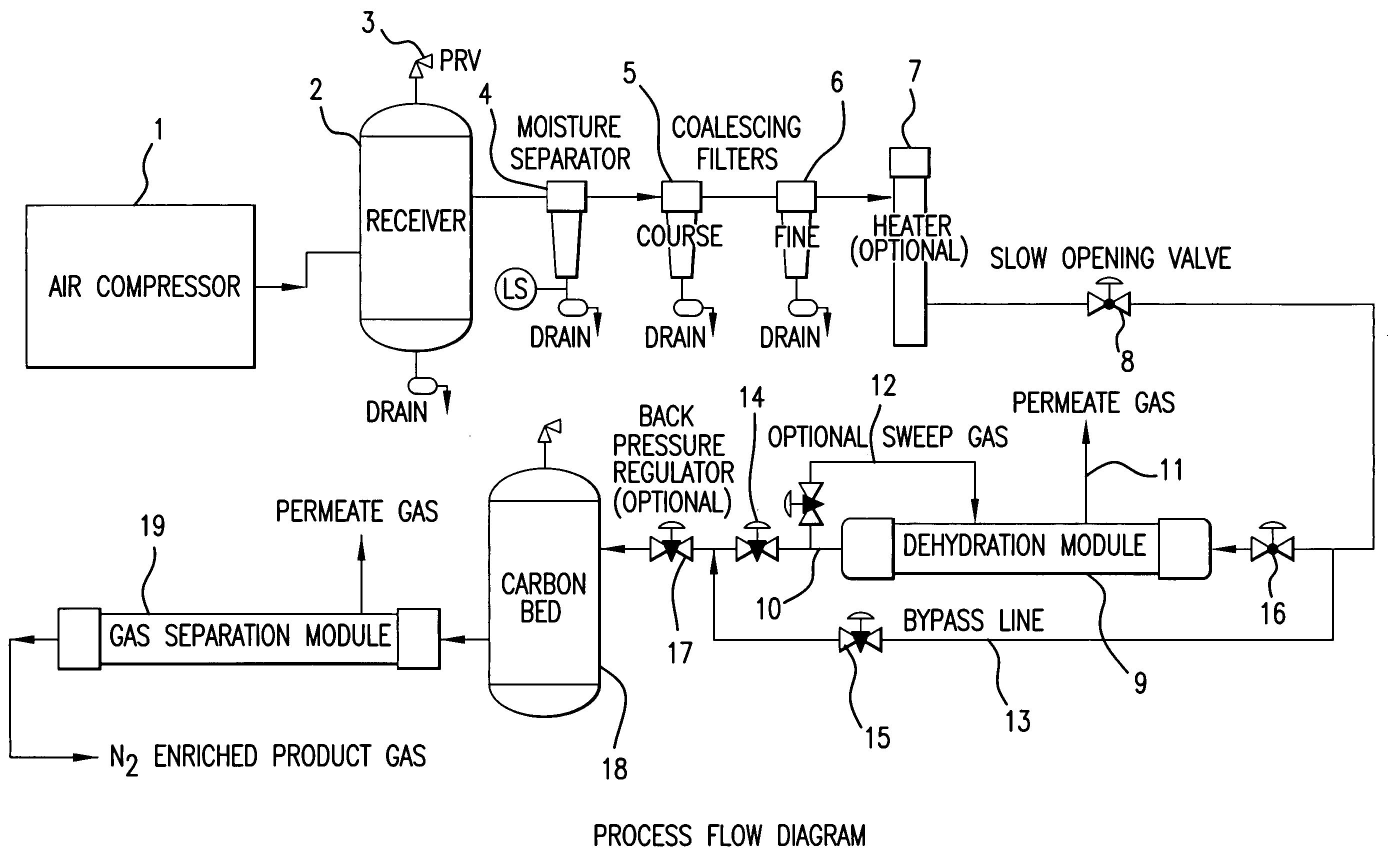
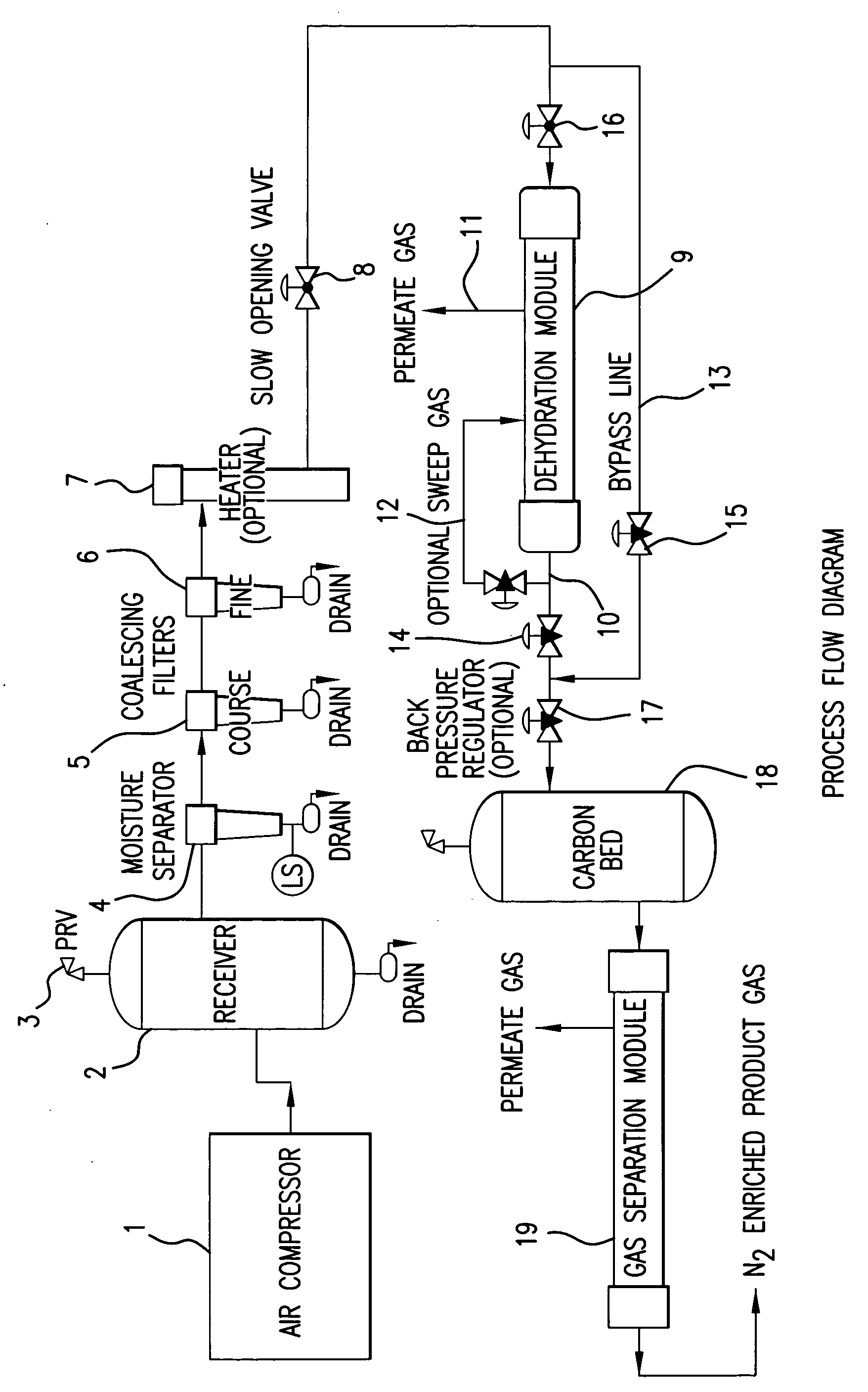
Air separation system using dehydration membrane for pretreatment of compressed air
a separation system and air technology, applied in the direction of separation process, dispersed particle separation, chemical apparatus and processes, etc., can solve the problems of reducing the efficiency and durability of the air separation system, system maintenance and periodic maintenance, and inherently consume energy, so as to improve the efficiency of the membrane-based or psa-based air separation system, reduce the cost of removing water, and reduce the cost
- Summary
- Abstract
- Description
- Claims
- Application Information
AI Technical Summary
Benefits of technology
Problems solved by technology
Method used
Image

Examples
example 1
[0044] Polysulfone polymer (product number UDEL P-1835, obtained from Solvay Plastics) was combined with tri-ethylene glycol (TEG) and n-methyl-pyrrolidinone (NMP) to form a spin dope that was extruded through a multi-filament hollow fiber die. The range of ratios of solvent (NMP) to non-solvent (TEG) can be from about 2.0 to about 4.0, with 2.5 being the preferred ratio. The polymer concentration range can be from about 40 to about 65% by weight, with 50% by weight being the preferred concentration. Die temperatures can range from about 75° C. to about 110° C., with 90° C. being the preferred spin temperature. Blowing a core gas through the center of an annular ring die forms the hollow fiber profile. The flow rate of the core gas can range from about 15 to about 30 SCCM, with 24 SCCM being preferred in order to achieve the desired fiber size of about 280 to about 350 microns for the outer diameter, and about 200 to about 250 microns for the inner diameter.
[0045] After the fiber w...
example 2
[0054] The process of Example 1 was repeated with an ultrafiltration fiber obtained from the Hydranautics Corporation. This fiber is commercially available, and is sold under the trademark HYDRACAP. The fiber has been used for water purification processes, and is categorized as a UF (ultrafiltration) membrane of Hydranautics Corp. The fiber is made of poly ether sulfone, instead of polysulfone. The fiber is quite large, having an outside diameter of 0.049 inches.
[0055] The fiber used in this Example is porous and hydrophilic, and has essentially no selectivity between oxygen and nitrogen. It has a high water vapor permeability relative to its permeability to air. Its pores have a size of the order of 100 to 1000 angstroms.
[0056] The fibers used in this Example are initially impermeable to air with no discernible air dehydration properties. The fiber must first be flushed with pressurized water to remove the water soluble pore filling material that is used in the storage of the fib...
example 3
[0059] Test devices were constructed to test the coated fibers described in Examples 1 and 2. The fibers were contained in copper tubing that was 38 inches long and 0.375 inches in diameter. The copper tubing had brass fittings at either end, with two fittings parallel to the module for connecting with the bore side of the fibers, and two fittings perpendicular to the fiber inset from tubesheets that connect to the shell-side of the fibers. Tubesheets at either end of the device were made with epoxy resins that, when cured, separated the bore side of the membranes from the shell-side. The latter arrangement allows for the isolated pressurization of either side of the membrane. The fibers made according to Example 1 had an outside diameter of 220 microns, and the test device used 180 fibers. These fibers are highly porous. The fibers used in Example 2 were much larger (having an outside diameter of 0.049 inches), and the test device contained only 6 such fibers. All test results are ...
PUM
 Abstract
Description
Claims
Application Information
 - R&D
- Intellectual Property
- Life Sciences
- Materials
- Tech Scout
- Unparalleled Data Quality
- Higher Quality Content
- 60% Fewer Hallucinations
Browse by: Latest US Patents, China's latest patents, Technical Efficacy Thesaurus, Application Domain, Technology Topic, Popular Technical Reports.
© 2025 PatSnap. All rights reserved.Legal|Privacy policy|Modern Slavery Act Transparency Statement|Sitemap|About US| Contact US: help@patsnap.com