Injectable structural adhesive

a structural adhesive and injection technology, applied in the direction of mechanical equipment, transportation and packaging, functional valve types, etc., can solve the problems of inability to provide enhanced structural support to the bonded rollover valve/fuel tank assembly, the peripheral bond may be susceptible to breaches or failures, and the hot plate welding is generally unsuitable for welding, etc., to achieve the effect of strengthening the structural suppor

Inactive Publication Date: 2005-10-27
DOW GLOBAL TECH LLC
View PDF41 Cites 0 Cited by
  • Summary
  • Abstract
  • Description
  • Claims
  • Application Information

AI Technical Summary

Benefits of technology

[0006] In accordance with the general teachings of the present invention, two or more components are preferably bonded together with an adhesive. The respective components are preferably brought into contact with one another such that an internal cavity is formed therebetween. On an external surface of one of the components, at least two apertures are preferably formed therein, wherein the apertures are preferably spaced and still more preferably opposed from each other. The adhesive is then preferably introduced through one of the apertures into the cavity. As more adhesive is introduced, the adhesive is preferably allowed or caused to flow through the cavity towards the location of the other aperture or apertures. Once the adhesive reaches the other aperture or apertures, the introduction of any additional adhesive is preferably ceased. The adhesive preferably substantially fills the entire volume of the cavity. Any air that was initially contained within the cavity is preferably removed by the flow of the adhesive. The adhesive is then preferably allowed to cure or harden, thus providing enhanced structural support to the bonded components in addition to providing, a bonding function between the components.

Problems solved by technology

Hot plate welding is generally unsuitable for welding large and irregularly shaped parts with difficult contours and joint lines.
This method suffers from several disadvantages in that the peripheral bond may be susceptible to breaches or failures, e.g., due to either improper welding techniques and / or the corrosive characteristics of the various fuels contained within the fuel tank.
Additionally, this method does not provide enhanced structural support to the bonded rollover valve / fuel tank assembly.

Method used


Image

  • Injectable structural adhesive
  • Injectable structural adhesive
  • Injectable structural adhesive

Examples


example i

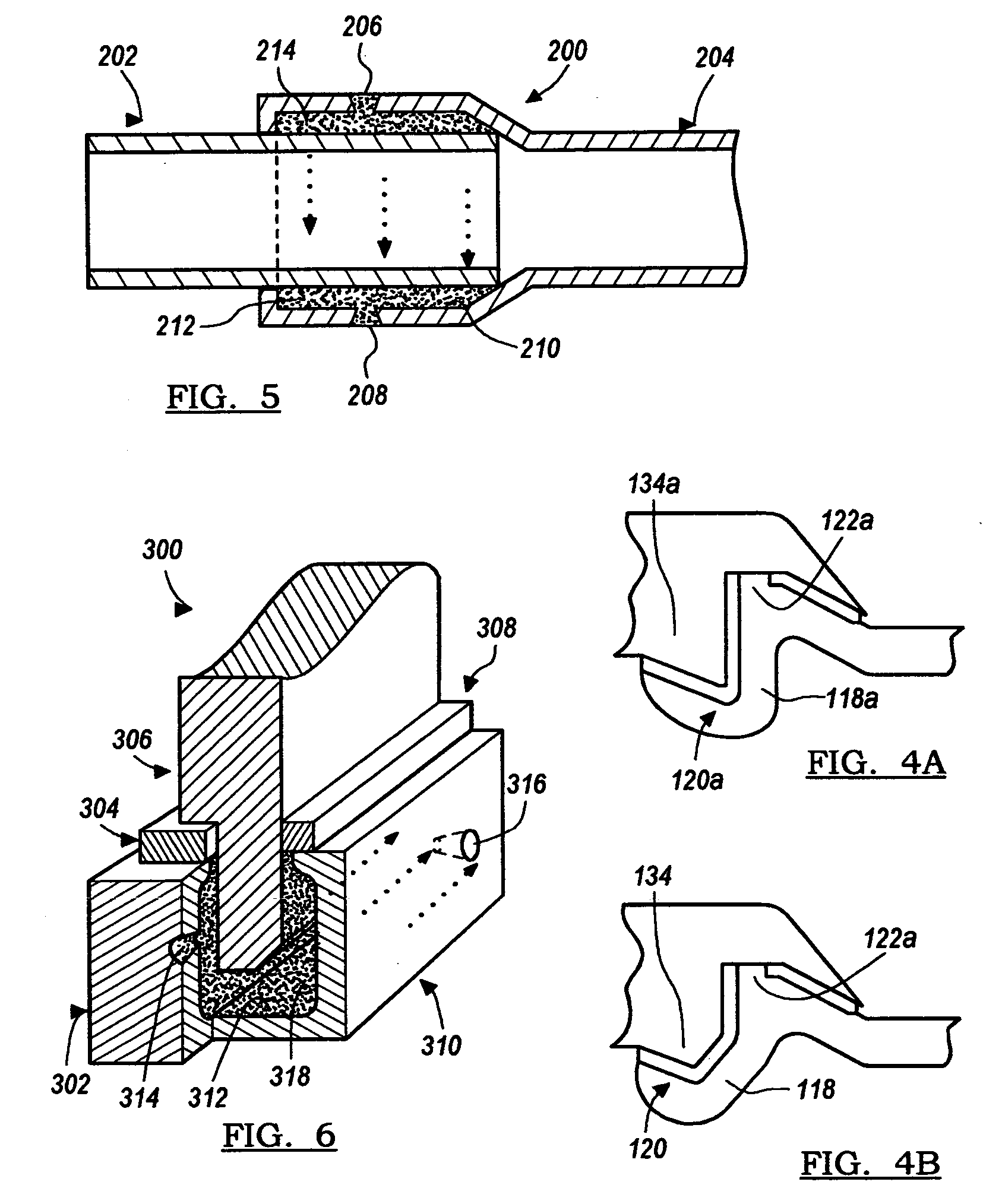
[0057] The flow of the adhesive was tested by mocking up a joint design using transparent plastic cups. The cups were placed one in the other with the outer cup having two apertures drilled at opposite ends. A two-part acrylic adhesive was injected in one aperture until it started coming out of the aperture on the other side. The adhesive had a Brookfield viscosity of 20,000 cps, as measured at 20 rpm with spindle number 7. A two-part pneumatic gun was used to dispense the adhesive at a pressure of 30 psi. There were two joints mocked up, one with a thickness of 0.7 mm and one with a thickness of 2 mm. The adhesive completely filled the cavity both times without any detectable air gaps.

[0058] In order to determine the strength of the resulting bonds between the components, the following test was performed, as described in Example II, below:

example ii

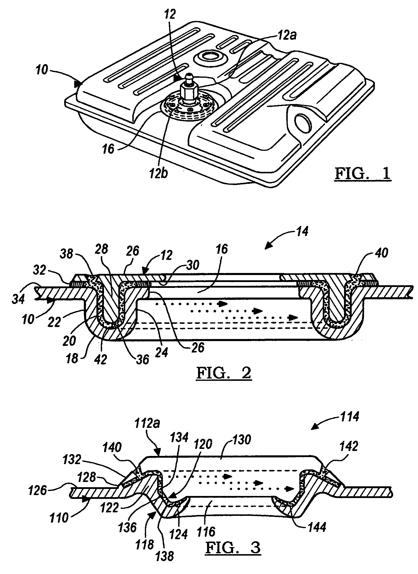
[0059] Three sample HDPE joints were mocked up with 7 mm thick HDPE, similar to the joints shown in FIG. 3. A two-part acrylic adhesive with a Brookfield viscosity of 50,000 cps was injected in one aperture, using a 2-part pneumatic gun at 40 psi, until it came out of the other aperture. The adhesive used was of the Low Energy Surface Adhesive (LESA) type and was obtained from Dow Chemical (Midland, Mich.) under the designations Lot Nos. 200302273-14-1 and 200302273--4-2. The adhesive was allowed to cure for 24 hours, and then, using an Instron machine, the upper part of the joint was pushed while the lower was constrained. In all three samples the HDPE failed in substrate failure mode. The force of failure for each sample was as follows: 2891 N, 3011 N, and 3176 N, respectively. After the joints failed, they were cut into four pieces to see how uniformly the respective cavities were filled. In all cases, there were no visible voids in the respective bond lines.


PUM

PropertyMeasurementUnit
angleaaaaaaaaaa
angleaaaaaaaaaa
pressureaaaaaaaaaa

Abstract

Injectable structural adhesives, methods of using the same, and products formed therewith, are described. The adhesive is introduced through a first opening into an internal cavity formed between two or more components. The adhesive is then permitted or forced to flow through the internal cavity, substantially filling the cavity, until it reaches a second spaced opening. Any air contained within the internal cavity is removed by the flow of the adhesive.

Description

FIELD OF THE INVENTION [0001] The present invention relates generally to injectable structural adhesives, and more particularly to injectable structural adhesives for joining components together that have an internal cavity formed therebetween, wherein the adhesive is injected into a first opening, the adhesive at least substantially filling the cavity, with any air in the cavity escaping through a spaced second opening. BACKGROUND OF THE INVENTION [0002] Automobile fuel tanks are typically comprised of various plastic materials, such as high-density polyethylene materials. Recently, the use of rollover valves, in conjunction with fuel tanks, has increased in order to prevent fuel from escaping the fuel tank, e.g., when a rollover accident has occurred. The rollover valve assembly typically includes a plastic surface or structure that is intended to mate (e.g., concentrically through a snap-fit configuration) with and be bonded to a corresponding structure or surface formed on, or n...

Claims


Application Information

Patent Timeline
Patent Type & Authority Applications(United States)
IPC IPC(8): B60K15/03B60K15/035C09J5/00C09J133/00C09J133/04
CPCB60K15/03177B60K15/03519C09J133/04Y10T428/24331Y10T137/0874Y10T137/0447C09J5/04C09J5/00C09J133/00
Inventor RISTOSKI, TONYMCMAKEN, MARCBREWSTER, CHRISTOPHERKORCHNAK, GREGORY
Owner DOW GLOBAL TECH LLC
Why Eureka
Try Eureka