Pad retaining clips

a technology of retaining clips and brake pads, which is applied in the direction of brake types, slack adjusters, braking elements, etc., can solve the problems of improper installation of brake elements, increased assembly costs and installation time, and improper re-installation of brake pads

Inactive Publication Date: 2005-10-27
AKEBONO BRAKE
View PDF7 Cites 71 Cited by
  • Summary
  • Abstract
  • Description
  • Claims
  • Application Information

AI Technical Summary

Benefits of technology

[0006] In the various embodiments of the present invention, a clip is disposed between a brake caliper with a brake pad channel and a brake pad with an edge member. The edge member moves in the brake pad channel between a rotor gap and a caliper housing. The clip further comprises a pad holding portion slidingly engaged w...

Problems solved by technology

In a large volume assembly process, it may be possible that the brake elements could be installed improperly, such that the friction members, for example, do not properly face the rotor.
The difficulty in keeping the brake pads installed and positioned properly in th...

Method used


Image

  • Pad retaining clips
  • Pad retaining clips
  • Pad retaining clips

Examples


Embodiment Construction

[0027] The following description of the various embodiments is merely exemplary in nature and is in no way intended to limit the invention, its application, or uses.

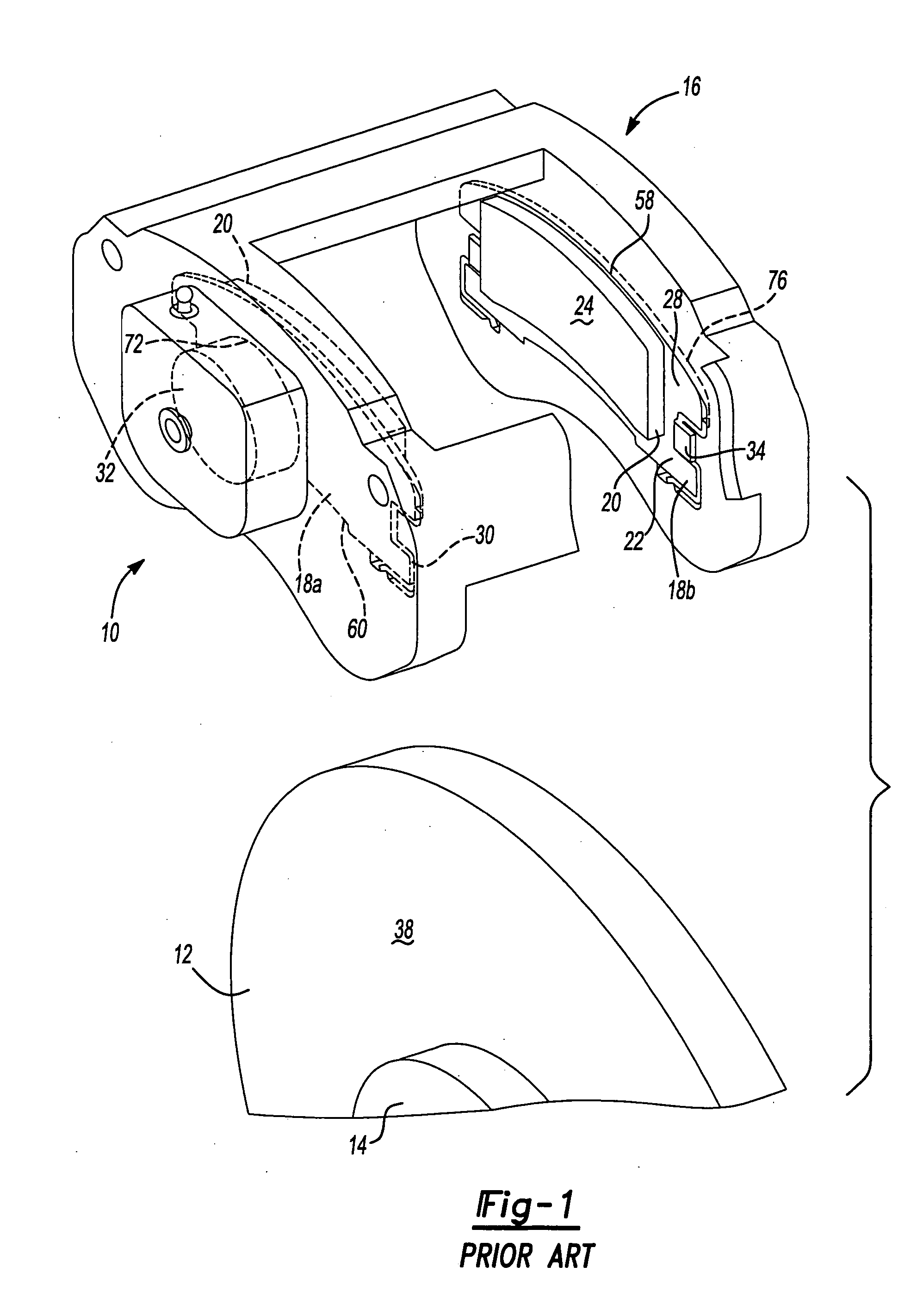
[0028] In FIG. 1, the various embodiments of the present invention are shown with reference to a simplified and exemplary vehicle disc brake system generally indicated by reference numeral 10. The disc brake system 10 includes a rotor 12 having a hub 14 configured to fit into a caliper 16. The disc brake system 10 also includes an inboard brake element 18a an outboard brake element 18b, respectively referred to hereinafter as brake elements 18 or may be referred to as brake pads 18 or disc brakes 18. It will be appreciated that the brake system 10 is shown in a simplified fashion and may be commonly referred to as a caliper assembly 10. To that end, a more detailed explanation of an exemplary disc brake system is disclosed in commonly assigned U.S. Pat. No. 4,351,421, titled Disc Brake filed Jul. 18, 1980, which is here...


PUM


Abstract

A brake caliper mounting clip is disposed between a brake caliper having a brake pad channel and a brake pad having an edge member. The edge member moves in the brake pad channel between a rotor gap and a caliper housing. The clip further comprises a pad holding portion slidingly engaged with the edge member and having a plurality of pad retaining members. The pad retaining members are connected to the pad holding portion and disposed between the edge member and the rotor gap. The plurality of the pad retaining members is further configured to prevent the brake pad from falling into the rotor gap. Additionally the edge member of the brake pad and the plurality of pad retaining members are configured to prevent improper installation of the brake pads in the caliper.

Description

FIELD OF THE INVENTION [0001] The present invention relates to a brake caliper mounting clip and, more particularly, to a plurality of brake pad retaining members formed on the mounting clip. BACKGROUND OF THE INVENTION [0002] In a conventional disc brake system, a pair of brake elements with friction members is slidably mounted on a caliper to forcibly press against a rotor to effect braking and slow the vehicle. Because the caliper moves the friction members into contact with the rotor surfaces, one or more mounting clips are installed between the brake elements and an interior of the caliper in order to reduce the sliding resistance. [0003] The disc brake systems are typically shipped with the brake elements and the mounting clips already installed in the caliper. Accordingly, a disc brake system customer simply installs the disc brake system onto the vehicle. It will be appreciated that in shipping, the rotor is absent from the brake system. Because the rotor is absent, the brak...

Claims


Application Information

Patent Timeline
IPC IPC(8): F16D65/097
CPCF16D65/0974
Inventor FAROOQ, MUHAMMAD
Owner AKEBONO BRAKE
Why Eureka
Try Eureka