
Power switch device

a power switch and power technology, applied in the direction of electric generator control, pulse technique, transportation and packaging, etc., can solve the problems of abnormal operation of portable electrical products, inability to further detect whether the input power is within a reasonable range,

Inactive Publication Date: 2005-10-27
ASIA OPTICAL CO INC
View PDF2 Cites 15 Cited by
  • Summary
  • Abstract
  • Description
  • Claims
  • Application Information

AI Technical Summary

Benefits of technology

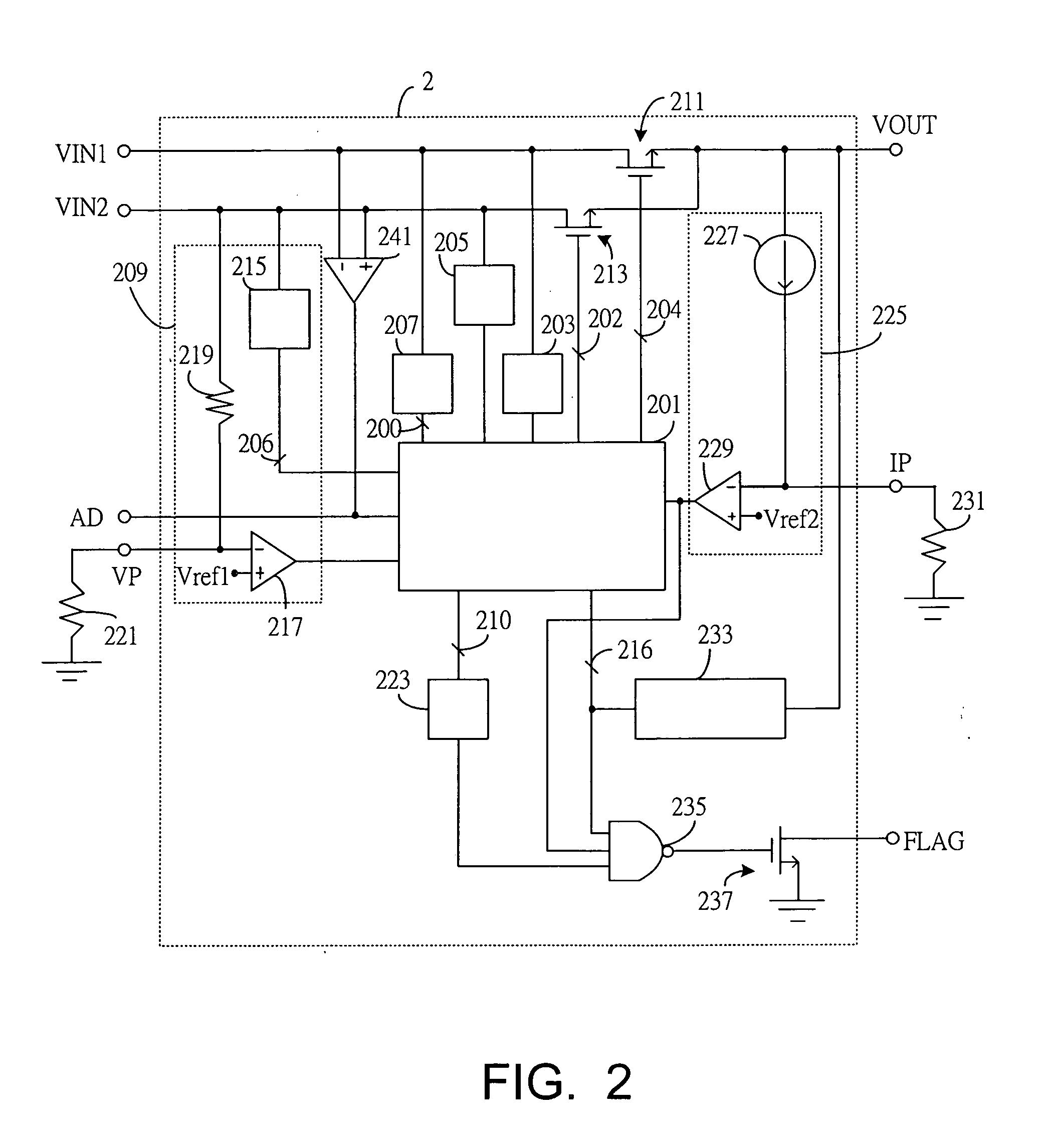
[0008] The present invention provides a power switch device which is configured to receive both a battery power and a public electricity, and, more particularly, to appropriately switch either a battery power or a public electricity to an output terminal of the power switch device for the portable electrical products. The portable electrical products described herein may include cell phone, PDA, digital camera, notebook and so on. The present invention detects whether the input voltage is within a reasonable range, and furthermore protects the portable electrical products.
[0014] Consequently, the power switch device of the present invention includes at least the following advantages: detection and appropriate switching of the input powers, over-high or under-low voltage protection, over-high current protection and over-high temperature protection.

Problems solved by technology

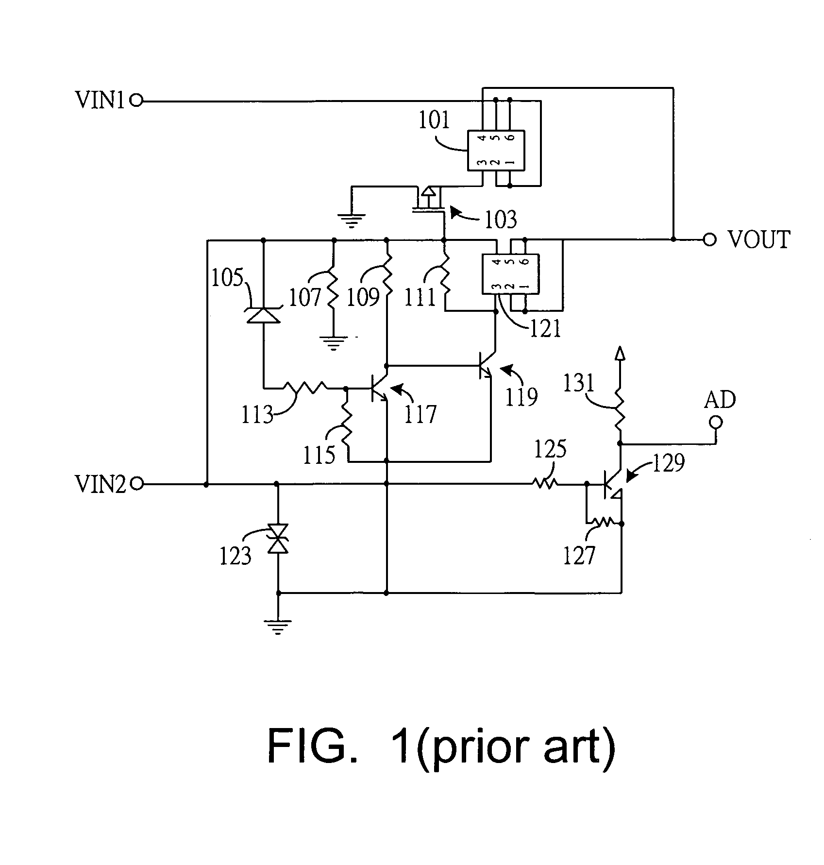
However, the prior art power switch device can only make switching according to the voltage level of the input terminal, and cannot further detect whether the input power is within a reasonable range.
Consequently, the prior art power switch device can not protect the portable electrical product from over-high voltage (or current) which may damage the internal circuits, and from over-low voltage (or current) which may result in abnormal operation of the portable electrical product.

Method used


Image

  • Power switch device
  • Power switch device
  • Power switch device

Examples


Embodiment Construction

[0017] In one embodiment of the present invention, with reference to FIG. 2, a power switch device 2 includes 5 input terminals and 3 output terminals. The 5 input terminals include a battery power input terminal (VIN1), a public electricity input terminal (VIN2), an over-voltage protection-setting terminal (VP), an over-current protection-setting terminal (IP), and a ground terminal (not illustrated in FIG. 2). The 3 output terminals include a power output terminal (VOUT), an abnormal status output terminal (FLAG), and a power status output terminal (AD). The battery power input terminal (VIN1) and the public electricity input terminal (VIN2) are respectively connected to a battery power and a public electricity. It should be noted that voltage of the public electricity, which is transmitted from the power company, is transformed and rectified appropriately by a pre-stage circuit before being transmitted to the public electricity input terminal (VIN2). The over-voltage protection-s...


PUM


Abstract

The power switch device, including a controller, an undervoltage lockout circuit (UVLO) and an input voltage detection circuit, is configured to appropriately switch either a battery power or a public electricity to a portable electrical product. The power switch device further includes a thermal sense circuit, a current detection circuit and an output voltage detection circuit to provide over-high or over-low voltage protection, over-high current protection and over-high temperature protection.

Description

CROSS REFERENCE TO RELATED APPLICATIONS [0001] This application claims priority to Taiwan Patent Application No. 093111219 entitled “Power Switch Device”, filed on Apr. 22, 2004. FIELD OF INVENTION [0002] The present invention generally relates to a power switch device with power protection function. BACKGROUND OF THE INVENTION [0003] With the progress of technology being well received by modern people, the portable electrical products (e.g., cell phone, PDA, digital camera, notebook computer, and so on) play important roles in people's life. In order to meet difference operation environments, these portable electrical products are usually designed to either use the battery power or the public electricity as their power sources. There is no problem for the portable electrical products when only one of the power sources exists. However, when both two power sources are connected to a portable electrical product, it is desirable to use a power switch device configured to appropriately ...

Claims


Application Information

Patent Timeline
Patent Type & Authority Applications(United States)
IPC IPC(8): H02P9/04
CPCH02J7/0068H03K17/005H03K2017/0806H03K17/693H03K17/0822
Inventor ZHANG, HENG
Owner ASIA OPTICAL CO INC
Learn More