Liquid crystal display device

a liquid crystal display and vertical alignment technology, applied in lighting and heating apparatus, instruments, light fastenings, etc., can solve the problem of difficult to dramatically improve achieve the effect of improving the response speed of the transmissive region, improving the efficiency of motion image display, and preventing discontinuity regions from contributing

Inactive Publication Date: 2005-10-27
SHARP KK
View PDF15 Cites 35 Cited by
  • Summary
  • Abstract
  • Description
  • Claims
  • Application Information

AI Technical Summary

Benefits of technology

[0016] The present invention has been achieved in view of the problem. An object of the present invention is to effectively enhance the response speed for display by the transmissive region with a simple configuration and improve motion image display performance.
[0017] As a result of intensive studies on vertical alignment liquid crystal display devices including rectangular transmissive regions, the inventors of the present invention have found by themselves that the response speed of the liquid crystal molecules is lowered at certain regions of the transmissive region.
[0035] The first substrate may be provided with a black matrix for preventing light from passing through regions between pixels and the light shield may be made of the same material as the black matrix.
[0037] According to the present invention, the discontinuity regions where the orientation of the liquid crystal molecules is unstable, which are visually observed during transmissive display, are identified and shielded from light. By so doing, the discontinuity regions are prevented from contributing to the transmissive display. That is, the regions where the response speed decreases are shielded from light so as to prevent the regions from contributing to the display, thereby improving the response speed of the transmissive region on the whole. This allows an improvement in motion image display performance with efficiency and achieves wide viewing angle and high contrast.

Problems solved by technology

As to the conventional vertical alignment liquid crystal display devices as described above, there is a problem of difficulty in dramatically improving response speed for display by the transmissive region.

Method used


Image

  • Liquid crystal display device
  • Liquid crystal display device
  • Liquid crystal display device

Examples


embodiment 1

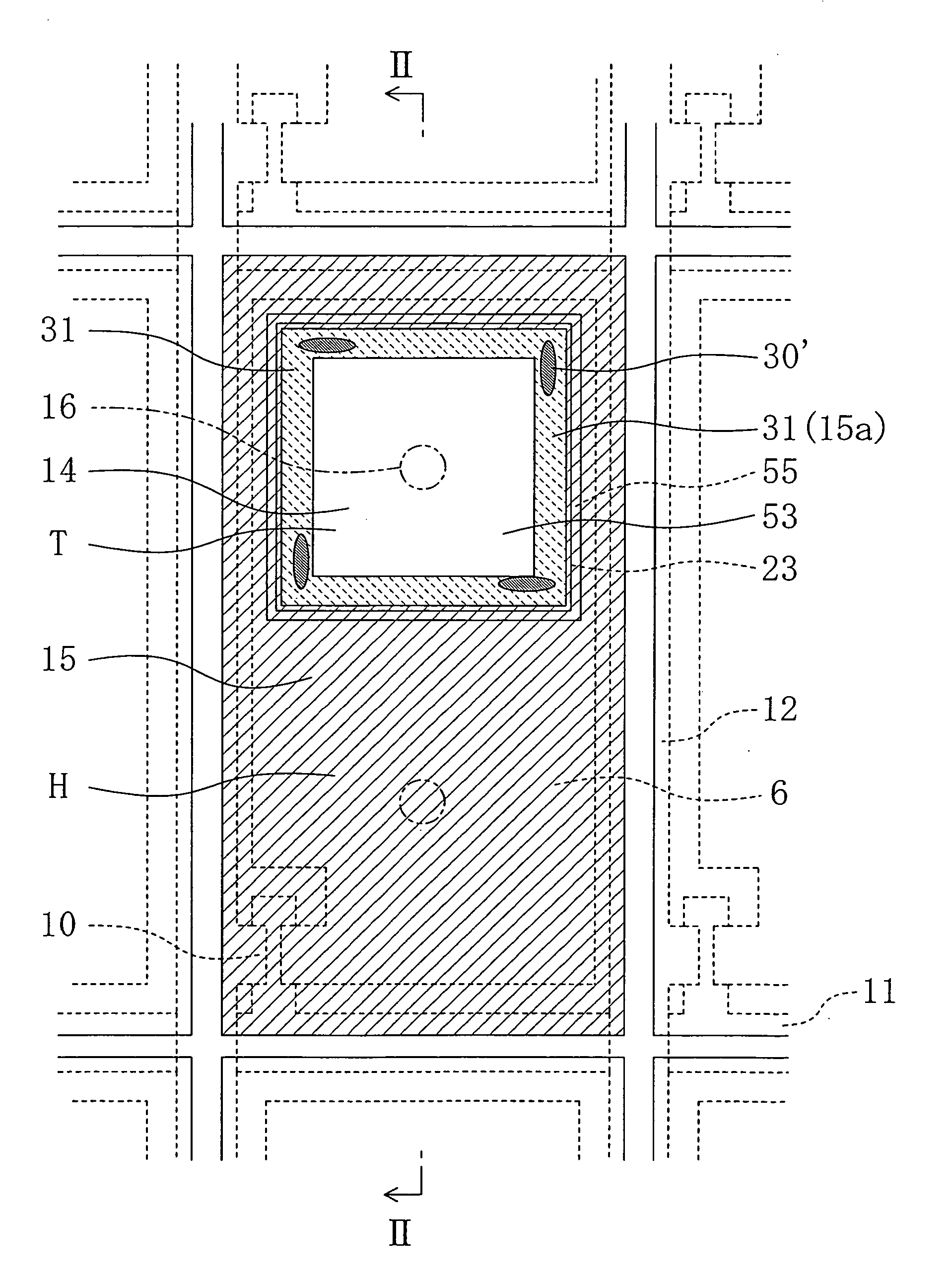
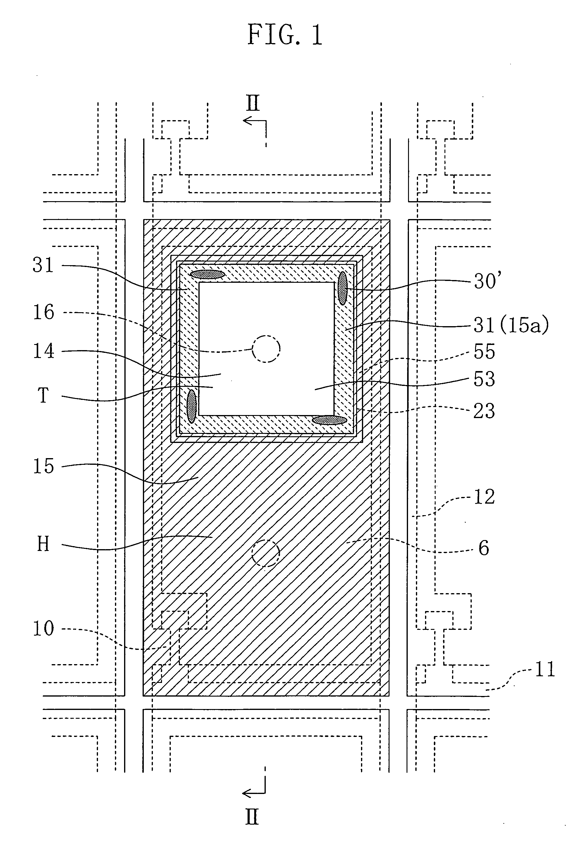
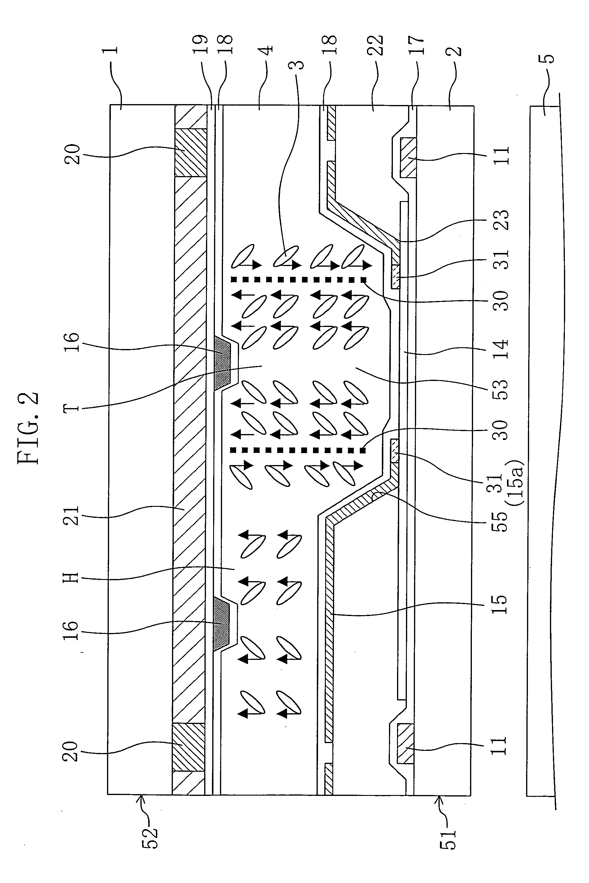
[0075]FIGS. 1 and 2 show a liquid crystal display device of Embodiment 1 of the present invention. FIG. 1 is an enlarged plan view illustrating a single pixel in the liquid crystal display device and FIG. 2 is a sectional view taken along the line II-II shown in FIG. 1.

[0076] As shown in FIG. 2, the liquid crystal display device includes a pair of substrates arranged opposite each other, i.e., a counter substrate 52 (a first substrate) and a TFT substrate 51 (a second substrate), a liquid crystal layer 4 interposed between the TFT substrate 51 and the counter substrate 52 and a backlight 5 which is arranged to face a surface of the TFT substrate 51 opposite to the counter substrate 52 and the liquid crystal layer 4. The liquid crystal display device further includes pixels 6 arranged in matrix configuration and TFTs 10 which are arranged one by one in each pixel and function as switching elements as shown in FIG. 1. Each of the pixels 6 of the liquid crystal display device includes...

embodiment 2

[0108] FIGS. 7 to 10 show a liquid crystal display device according to Embodiment 2 of the present invention. In the following embodiments, components same as those shown in FIGS. 1 to 6 are given with the same reference numerals and a detailed explanation thereof is omitted.

[0109] A liquid crystal display device of this embodiment includes light shields 31 which prevent light from passing through regions at the four corner regions of the aperture 53 as shown in FIG. 7.

[0110] The inventors of the present invention have identified regions where the response speed of the liquid crystal molecules 3 decreases. Accordingly, they provided the light shields 31 at the certain regions 30′ where the liquid crystal molecules 3 are oriented in a discontinuous maimer.

[0111] As shown in FIG. 7, each of the light shields 31 is in the form of an elongated rectangle when viewed in plan and arranged along the sides of the aperture 53 (the transmissive region T). One of the long sides and one of th...

embodiment 3

[0119] FIGS. 12 to 16 show a liquid crystal display device according to Embodiment 3 of the present invention.

[0120] In the foregoing embodiments, the aperture 53 is in the form of a square when viewed in horizontal cross section. In this embodiment, however, the aperture 53 is in the form of an elongated rectangle when viewed in horizontal cross section. That is, the transmissive region T is shaped into an elongated rectangle when viewed in plan.

[0121] As shown in FIG. 11, the elongated rectangular aperture 53 changes the shape of the discontinuity regions 30′ in which the liquid crystal molecules 3 are oriented in a discontinuous manner. More specifically, two of the four discontinuity regions 30′ generated along the long sides of the elongated rectangular aperture 53 are relatively elongated along the long sides of the aperture 53.

[0122] Accordingly, in this embodiment, the light shields 31 formed along the long sides of the aperture 53 are also elongated more than the light s...


PUM

PropertyMeasurementUnit
acute angleaaaaaaaaaa
longitudinal lengthaaaaaaaaaa
sizeaaaaaaaaaa

Abstract

A vertical alignment liquid crystal display device includes: a pair of substrates which are arranged opposite each other; a liquid crystal layer which is interposed between the paired substrates; an interlayer insulating film which is formed on at least either the first substrate or the second substrate and provided with an aperture which is rectangular when viewed in plan and opened toward the other substrate; a transmissive region provided within the periphery of the aperture and performs transmissive display; and a reflective electrode which is arranged along the periphery of the aperture. The liquid crystal display device further includes a light shield for preventing light from passing through discontinuity regions which are included in a portion of the liquid crystal layer corresponding to the aperture and where liquid crystal molecules are oriented in a discontinuous manner.

Description

CROSS-REFERENCE TO RELATED APPLICATION [0001] This non-provisional application claims priority under 35 U.S.C. §119(a) on Japanese Patent Applications Nos. 2004-128812 filed on Apr. 23, 2004 and 2005-111788 filed on Apr. 8, 2005, the entire contents of which are hereby incorporated by reference. BACKGROUND OF THE INVENTION [0002] (a) Field of the Invention [0003] The present invention relates to a vertical alignment liquid crystal display device including transmissive regions for transmissive display. [0004] (b) Description of Related Art [0005] So far, there have been known semi-transparent liquid crystal display devices including reflective regions for reflective display and transmissive regions for transmissive display (e.g., see Japanese Unexamined Patent Publication No. 2003-195329). Now, an explanation is given of a semi-transparent liquid crystal display device with reference to the drawings. [0006] One of pixels in a vertical alignment semi-transparent liquid crystal display...

Claims


Application Information

Patent Timeline
Patent Type & Authority Applications(United States)
IPC IPC(8): G02F1/1333G02F1/1335G02F1/13357G02F1/1337G02F1/1343G02F1/139
CPCG02F1/133512G02F1/133555G02F2001/133742G02F1/1393G02F2001/13373G02F1/133707G02F1/13373G02F1/133742F21V17/104
Inventor FUJIOKA, KAZUYOSHISONODA, TOORU
Owner SHARP KK
Why Eureka
Try Eureka