Battery and battery terminal structure and method of manufacture

a technology of battery and terminal structure, applied in the direction of vent arrangement, cell components, cell component details, etc., can solve the problems of difficult to achieve a proper and effective seal against battery acid leakage, leakage problems, and damage to the battery acid

Inactive Publication Date: 2005-10-27
KAUPTHING BANK HF AS AGENT +1
View PDF67 Cites 46 Cited by
  • Summary
  • Abstract
  • Description
  • Claims
  • Application Information

AI Technical Summary

Benefits of technology

[0015] The present invention overcomes problems caused by concentric misalignment and / or non-uniform force applied to the seal, as well as problems associated with the use of high torque applied to the collar to draw the terminal post and components within the battery case securely up against the lid. With the present invention the seal is located between the collar and strap so that the collar applies a uniform force against the seal. There are no concentricity problems because the collar, which applies the force for the seal, is mounted to the terminal post such that concentricity between these components is insured. Also, the torque applied to the collar need be only sufficient to effect a seal between the collar and strap.

Problems solved by technology

The battery acid can also be very destructive and harmful should it leak from the battery casing.
With such prior art terminal constructions it was difficult to achieve a proper and effective seal against leakage of the battery acid around the terminal post.
If the post was not perpendicularly oriented relative to the lid surface surrounding the post, the collar applied uneven force to the lid which thereby applied uneven force on the seal causing leakage problems.
Similarly, if the seal was of the type that sealed in a generally radial direction, it was required that the lid and terminal surfaces between which the seal was places be concentric requiring precise concentric alignment of these components which was difficult to achieve.
Without precise concentricity, battery acid leakage past the seal could occur.

Method used


Image

  • Battery and battery terminal structure and method of manufacture
  • Battery and battery terminal structure and method of manufacture
  • Battery and battery terminal structure and method of manufacture

Examples


Embodiment Construction

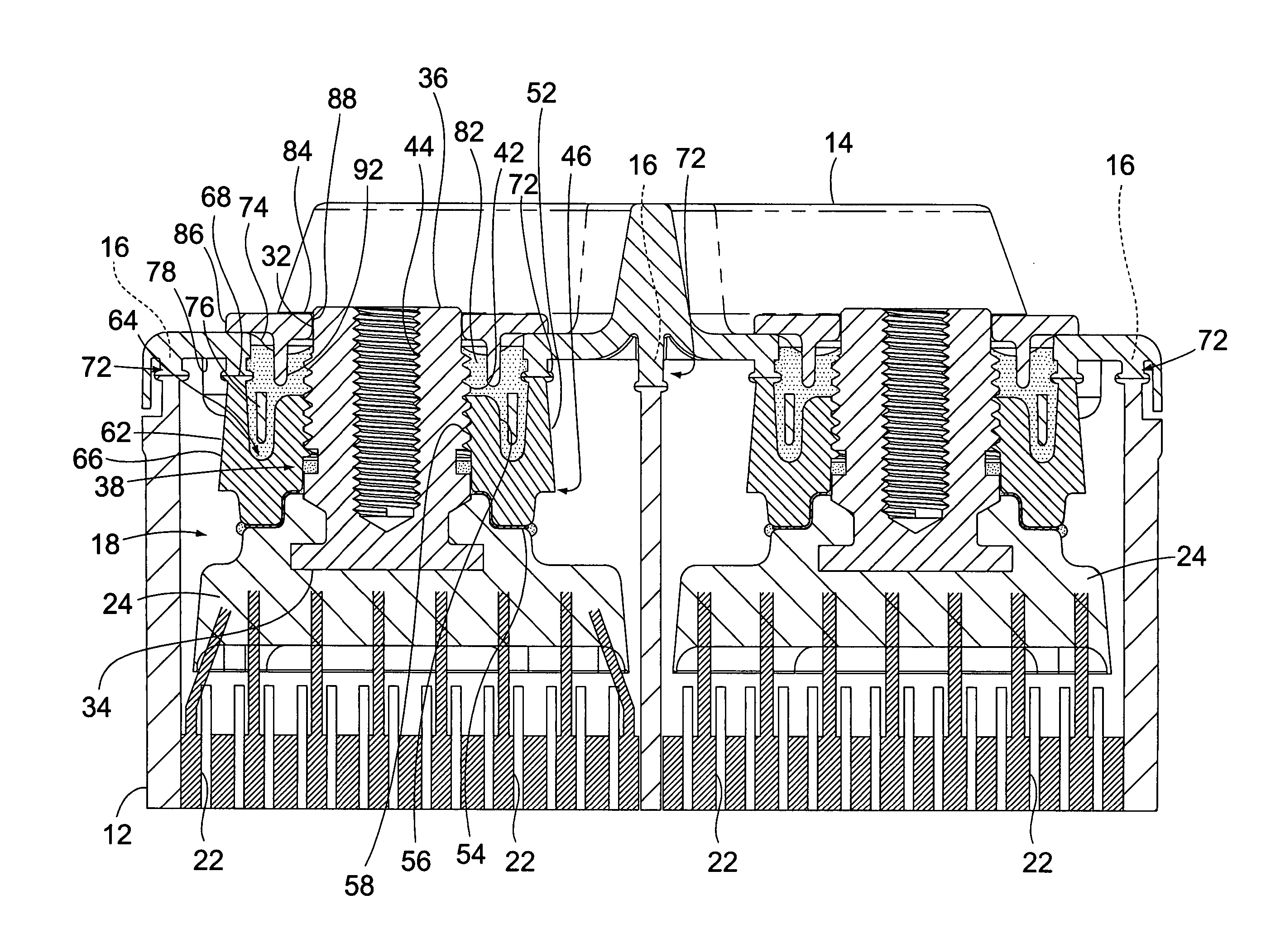
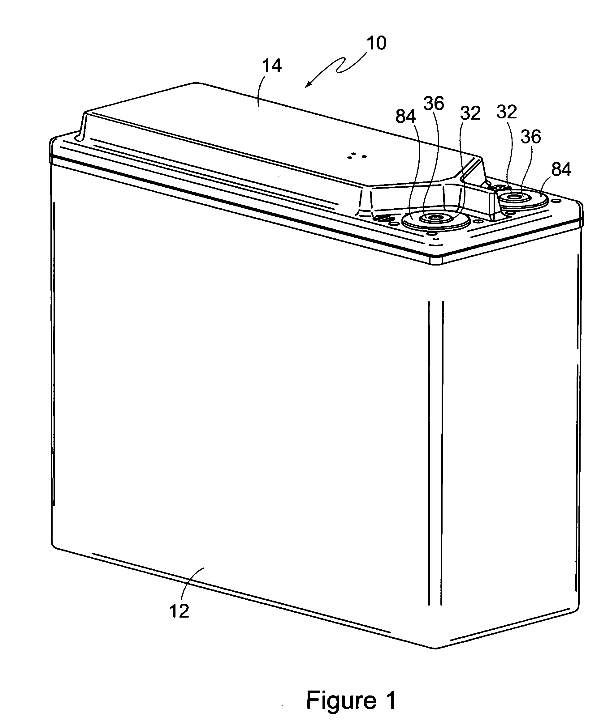
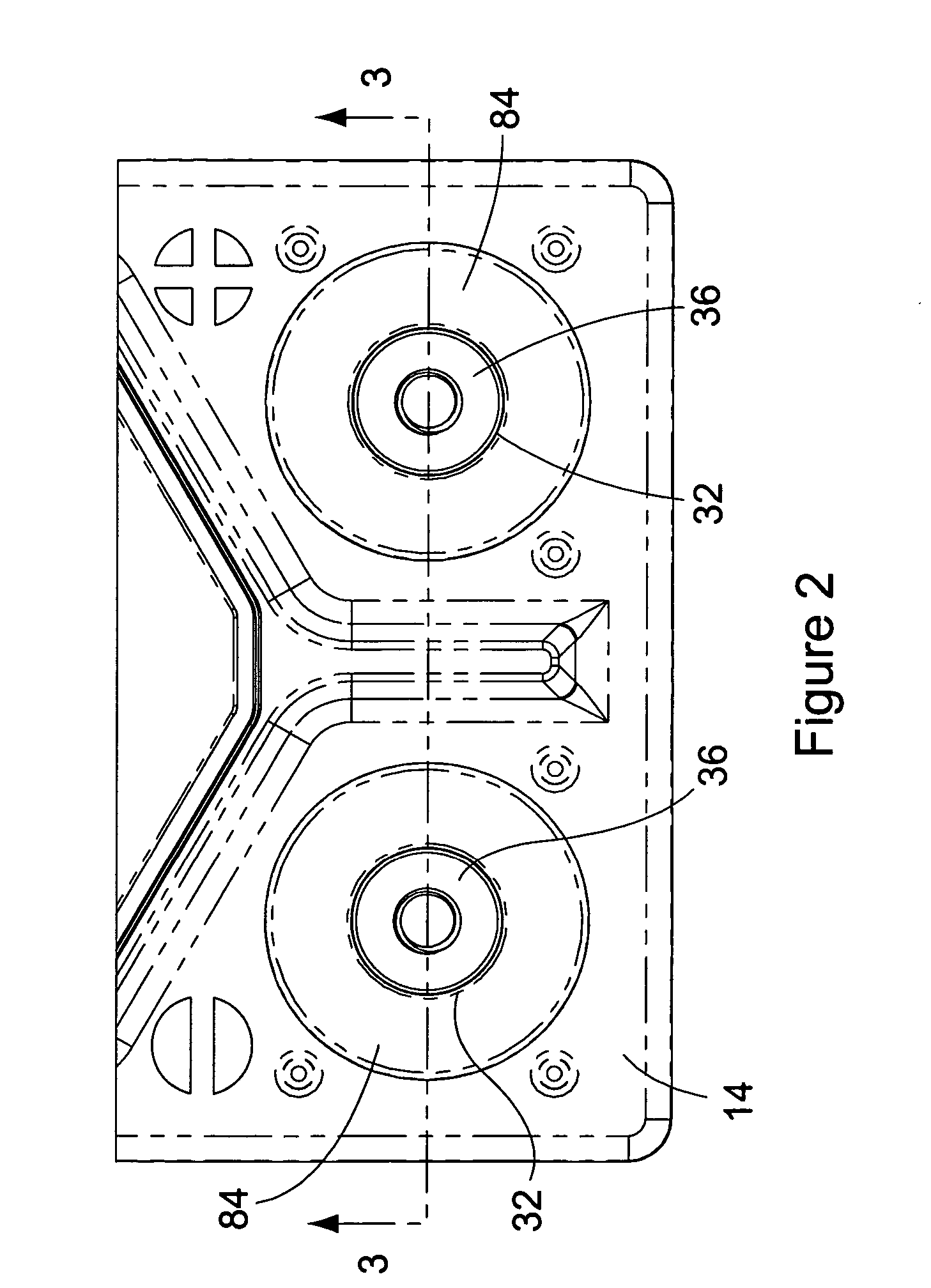
[0031] With reference to the drawings, there is shown a battery 10 in accordance with a preferred embodiment of the invention. The battery 10 has a casing comprising a battery box 12 and a lid 14. The casing is constructed of materials typically employed in the construction of battery casings and particularly batteries of the lead-acid type to which the present invention is primarily directed. The battery box 12 has a rectangular top edge 16 that surrounds a top access opening into the battery box interior 18. The lid 14 has a rectangular configuration that is dimensioned to fit over the battery box top edge 16.

[0032] A plurality of battery plates 22 are contained in the battery box interior 18, as shown in FIG. 3. The plates 22 of like polarity are interconnected by a lead or lead alloy plate strap 24 as is conventional in the lead-acid battery art. Battery acid is contained within the plates and the interior of the casing as is also conventional with a lead-acid battery.

[0033] A...


PUM

PropertyMeasurementUnit
lengthaaaaaaaaaa
perimeteraaaaaaaaaa
interior volumeaaaaaaaaaa

Abstract

The construction of an electrically conductive terminal of a lead-acid battery seals a terminal post from the acid in the battery box interior by an collar that is mounted on the exterior of the terminal and that sandwiches a seal between the collar and a plate strap of the battery in the interior of the battery box. The collar is sealed to the battery casing.

Description

BACKGROUND OF THE INVENTION [0001] (1) Field of the Invention [0002] The present invention is directed to a battery construction and method of manufacture, and more particularly a terminal structure for a lead-acid battery that provides improved sealing that prevents the acid within the battery from leaking from the battery casing and from contacting the terminal. [0003] (2) Description of the Related Art [0004] In the design of lead-acid batteries, i.e. batteries having a plurality of lead or lead alloy plates in a solution of sulfuric acid, sealing the battery casing and the electrically conductive terminals of the battery are primary considerations. The electrically conductive terminals are often constructed of brass or other similar metal that can react and corrode when exposed to the acid of the battery. The battery acid can also be very destructive and harmful should it leak from the battery casing. It is therefore necessary that the construction of the lead-acid battery insur...

Claims


Application Information

Patent Timeline
Patent Type & Authority Applications(United States)
IPC IPC(8): H01M10/06H01M50/171H01M50/172H01M50/184H01M50/188H01M50/55H01M50/552H01M50/567
CPCH01M2/0434H01M2/06H01M2/08Y10T29/4911H01M2/30H01M10/06H01M2/12Y02E60/10H01M50/172H01M50/30H01M50/184H01M50/171H01M50/567H01M50/552H01M50/55H01M50/188
Inventor HOOKE, JOHN WILLARDFLEMING, FRANK ALBERT
Owner KAUPTHING BANK HF AS AGENT
Why Eureka
Try Eureka