Sternal closure device and method

a technology of sternal closure and sternum, which is applied in the field of surgical devices, can solve the problems of sternal closure, breakage, wire suture hardening and breakage, and surgeons typically do not have the means to ensur

Active Publication Date: 2005-10-27
ETHICON INC
View PDF56 Cites 134 Cited by
  • Summary
  • Abstract
  • Description
  • Claims
  • Application Information

AI Technical Summary

Problems solved by technology

There are numerous drawbacks with the use of wire sutures.
For example, surgeons typically do not have means for ensuring that the tension in one wire suture is the same as the tension in another.
Another drawback is that excessive twisting of the wire suture during tensioning can also result in hardening of the wire suture and breakage during the sternal closure procedure or after the surgical procedure.
After being twisted together, the excess wire suture must be cut away, leaving sharp ends which may be palpable through the skin, painful and cosmetically undesirable.
Moreover, the use of devices such as clamps, etc., that completely wrap around the sternum may irritate or damage tissue and vital structures such as blood vessels, particularly on the underside of the sternum.
Another drawback with the use of wire suture is that the amount of force necessary to close the sternum may cause the wire suture, which has a very small load-bearing surface, to cut through the cortical and cancellous portions of sternum.
Additionally, the wire suture may cut through the cortical and cancellous portions of the sternum after sternal closure has been achieved, particularly when the wire sutures are subjected to intermittent severe loading due to coughing and other movements of the patient.
In some cases, this results in a loosening of a wrapped wire suture or an enlargement of the pierced holes in the sternum when the wire suture is pierced through the sternal halves.
Such an infection in the sternum is associated with significant morbidity and sometimes death.
None of the devices described above that utilize wire sutures offers protection from shear loading and the resultant axial motion of the sternal halves.

Method used


Image

  • Sternal closure device and method
  • Sternal closure device and method
  • Sternal closure device and method

Examples


Embodiment Construction

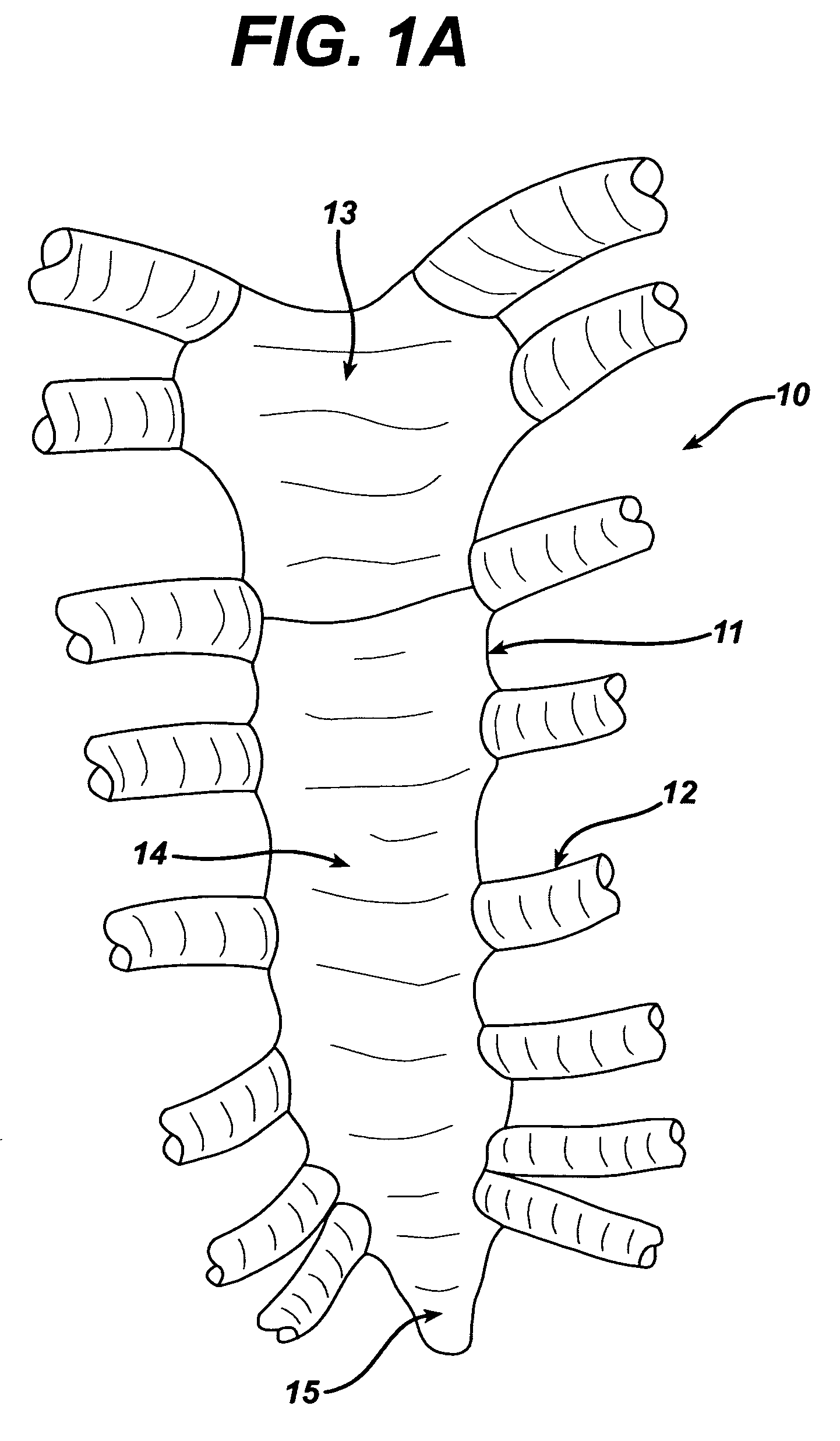
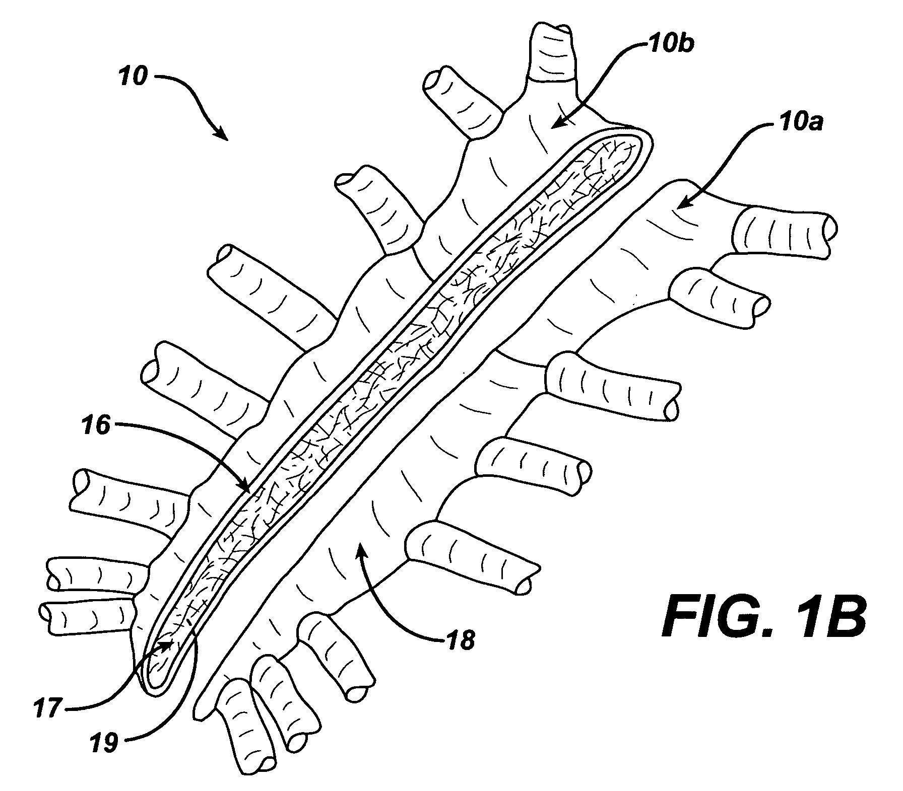
[0027] The device will now be described by way of example only and not to limit the spirit or scope of the present invention. Referring now to FIG. 1A, a human sternum generally referred to by reference numeral 10 is shown along with intercostal spaces 11, ribs 12 near the attachment point to the sternum, manubrium 13, body 14, and xyphoid process 15. FIG. 1B illustrates the sternum 10 after a median sternotomy has been performed. The sternum 10 is split into a first portion 10a and a second portion 10b. The cortical surface 16 and cancellous surface 17 of a portion of the sternal incision margin is also illustrated. Also illustrated are the anterior surface 18 and posterior surface 19 of the sternum 10.

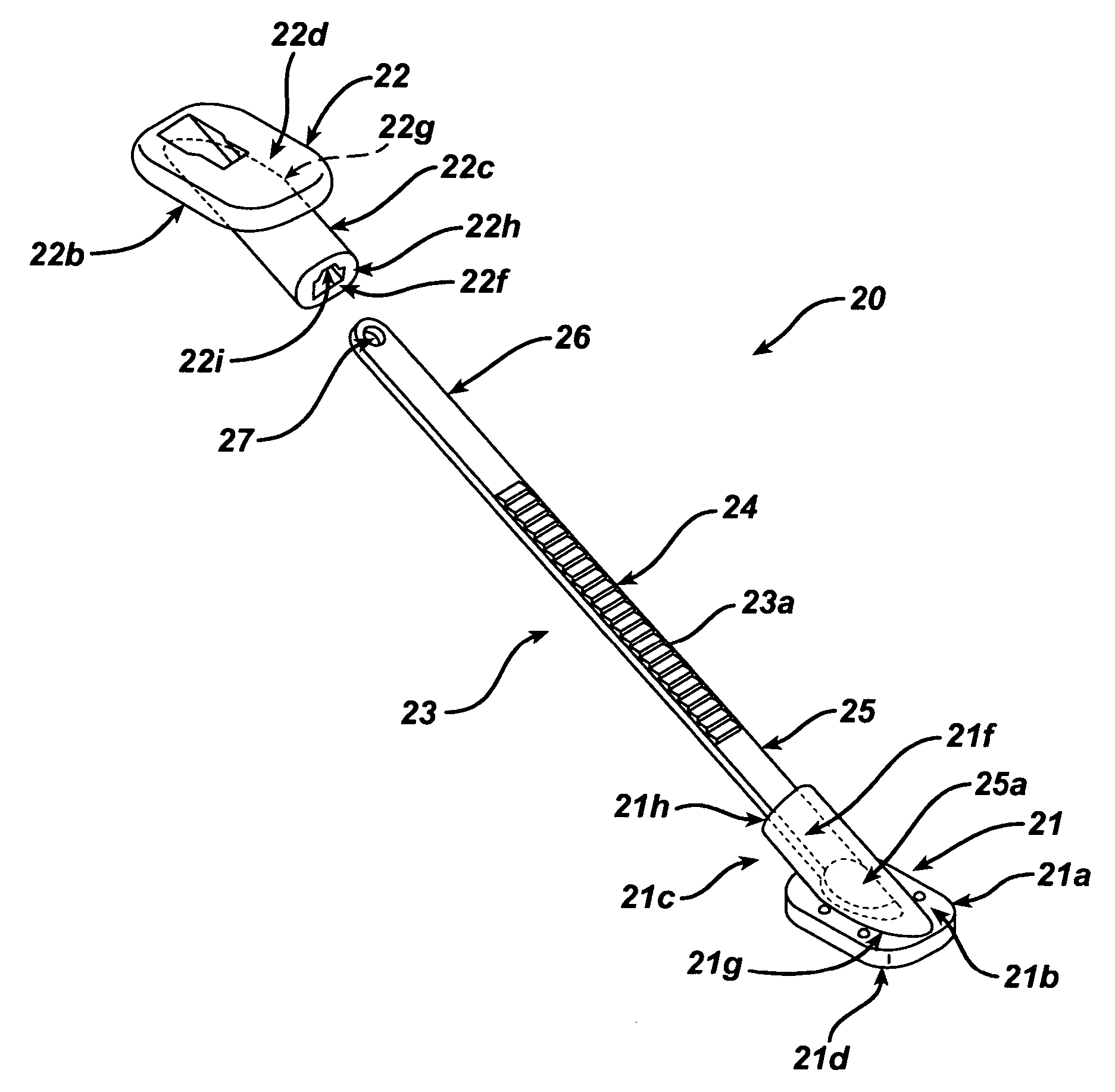
[0028] Referring now to FIG. 2, the sternal closure device is generally referred to by reference numeral 20 and includes a first bearing member 21, a second bearing member 22, and a sternum joining member 23 having an axis 24, a first end 25 and a second end 26. The first bearing me...


PUM


Abstract

A device and method for joining a severed sternum is disclosed. The device includes first and second bearing members, a sternum joining member having an axis and first and second ends, the first end connected to the first bearing member, the second bearing member adapted to engage the sternum joining member, and the sternum joining member is adapted to traverse the exposed cancellous surfaces of the sternal portions. The method includes moving the second bearing member along the axis of the sternum joining member toward the first bearing member, with the sternum joining member traversing the cancellous surfaces of both sternal portions, and securing the second bearing member on the axis of the sternum joining member so that the severed sternum is securely closed. A kit including sternal closure devices and other tools for closing a sternotomy is also disclosed.

Description

BACKGROUND OF THE INVENTION [0001] The present invention relates generally to surgical devices for the repair of split portions of tissue, in particular, to surgical devices for closing a severed sternum. [0002] The sternum is an elongated, flattened bone, forming the middle portion of the anterior wall of the thorax. Its upper end supports the clavicles, and its margins articulate with the cartilages of the first seven pairs of ribs. It consists of three parts, named from the neck downward, the manubrium, the body, and the xiphoid process. Its average length in an adult is about 17 cm, and is slightly less in a female adult. The sternum is a composite bone structure with a thin cortical shell surrounding a low-density cancellous core. Cortical bone is ivory-like and is dense in texture without cavities. It is the shell of many bones, surrounding the cancellous bone in the center. Cancellous bone is sponge-like with numerous cavities. [0003] During surgery involving thoracic organs ...

Claims


Application Information

Patent Timeline
Patent Type & Authority Applications(United States)
IPC IPC(8): A61B17/56A61B17/68A61B17/82
CPCA61B17/823A61B17/683
Inventor ROUSSEAU, ROBERT A.WEADOCK, KEVIN S.CHATLYNNE, ETAN S.
Owner ETHICON INC
Why Eureka
Try Eureka