Vehicle periphery display control system

a display control and vehicle periphery technology, applied in the direction of navigation instruments, pedestrian/occupant safety arrangements, instruments, etc., can solve the problem that the conventional vehicle periphery monitoring device cannot change the displayed imag

Inactive Publication Date: 2005-10-27
DENSO CORP
View PDF8 Cites 81 Cited by
  • Summary
  • Abstract
  • Description
  • Claims
  • Application Information

AI Technical Summary

Problems solved by technology

Therefore, the conventional vehicle periphery monitoring device is unable to change displayed images depending on the running state of the vehicle that is not related to the operation of the turn indicator.

Method used


Image

  • Vehicle periphery display control system
  • Vehicle periphery display control system
  • Vehicle periphery display control system

Examples


Embodiment Construction

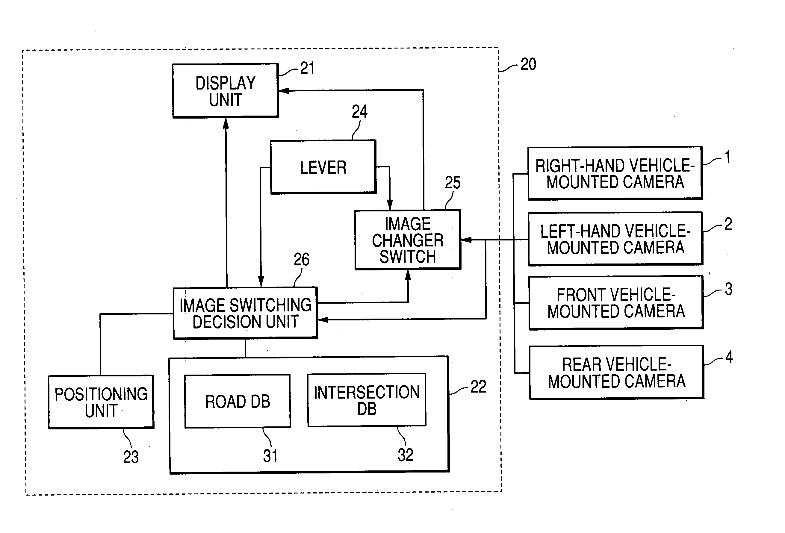
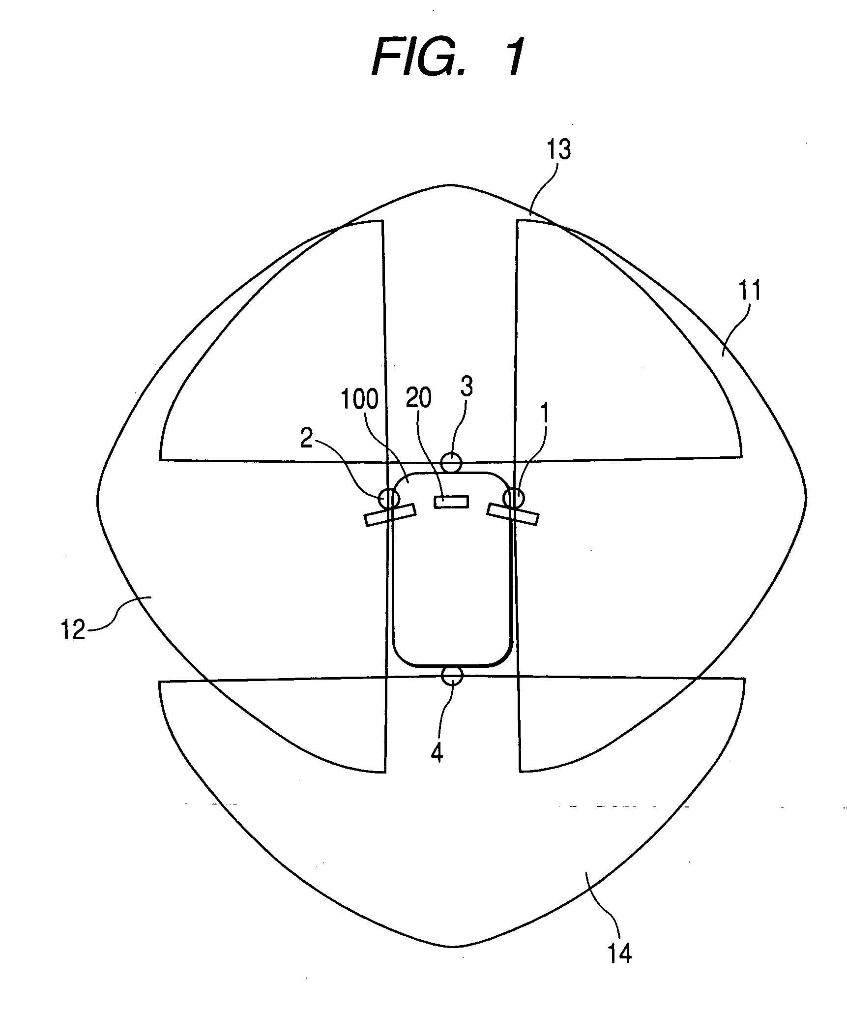
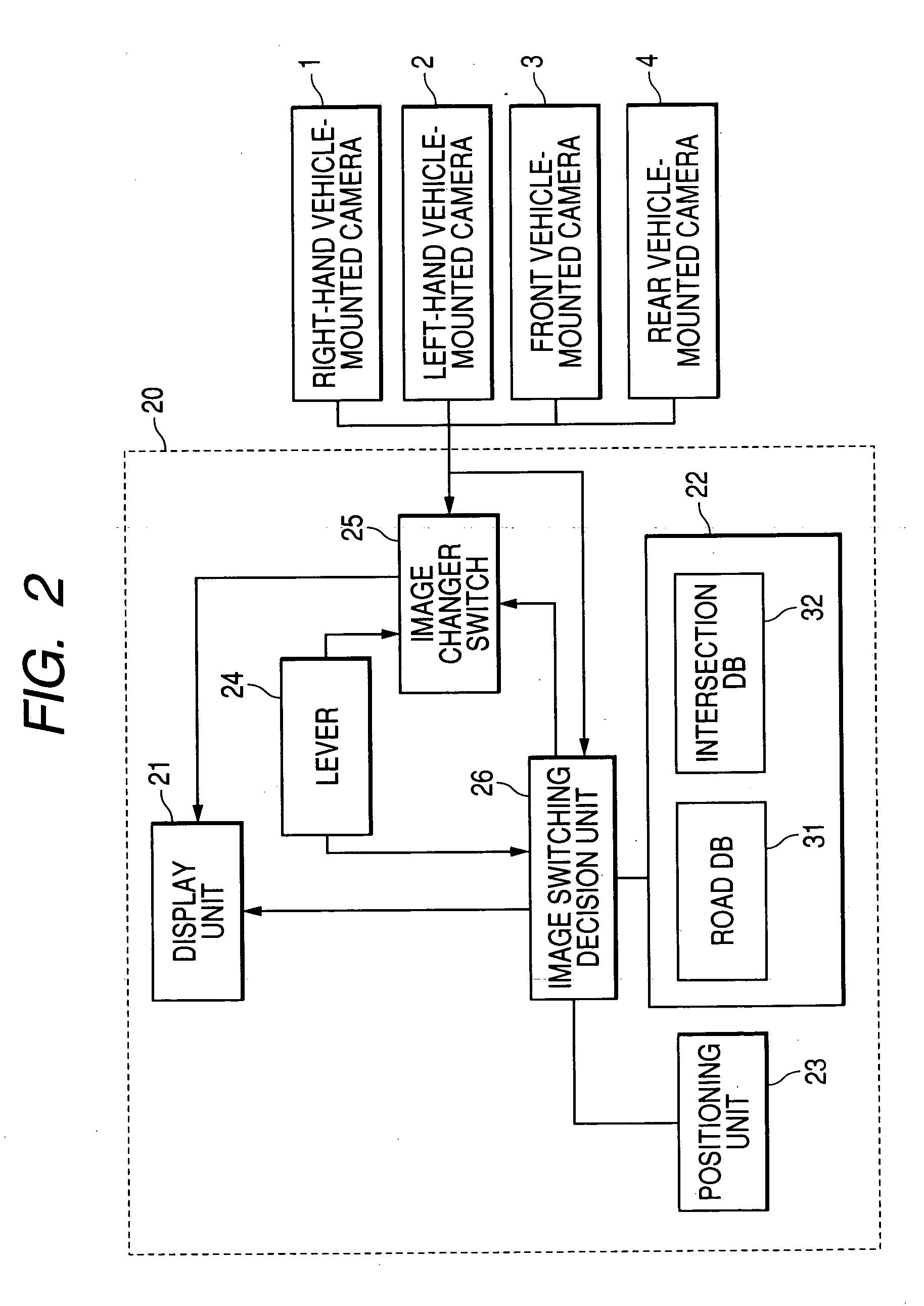
[0037]FIG. 1 shows a vehicle 100 incorporating a vehicle periphery display control system 20 according to an embodiment of the present invention.

[0038] As shown in FIG. 1, the vehicle 100 carries four cameras, i.e., a right-hand vehicle-mounted camera 1, a left-hand vehicle-mounted camera 2, a front vehicle-mounted camera 3, and a rear vehicle-mounted camera 4. The cameras 1 through 4, which are typically video cameras, are mounted in respective different positions on the vehicle 100.

[0039] Specifically, the right-hand vehicle-mounted camera 1 is positioned near the right-hand door mirror of the vehicle 100, and the left-hand vehicle-mounted camera 2 is positioned near the left-hand door mirror of the vehicle 100. The front vehicle-mounted camera 3 is positioned on the front end of the vehicle 100, and the rear vehicle-mounted camera 4 is positioned on the rear end of the vehicle 100.

[0040] Each of the cameras 1 through 4 has a fish-eye lens for capturing an image of a peripheral...


PUM


Abstract

A vehicle periphery display control system displays peripheral images of a vehicle which are captured by a plurality of cameras mounted on the vehicle in respective different positions thereon. A storage medium stores road configuration information of a road. A positioning unit identifies the present position of the vehicle on the road. A image switching decision unit selects either one of images captured by the cameras based on specific road configuration information of a peripheral area around the vehicle, which includes the present position identified by the present position identifying unit, of the road configuration information stored in the storage medium. The image switching decision unit controls a display unit to display the image selected by the selecting unit.

Description

CROSS-REFERENCE TO RELATED APPLICATIONS [0001] This application is based upon and claims the benefits of priority from the prior Japanese Patent Application No. 2004-126527, filed on Apr. 22, 2004, the entire contents of which are incorporated herein by reference. BACKGROUND OF THE INVENTION [0002] 1. Field of the Invention [0003] The present invention relates to a vehicle periphery display control system for displaying images of the periphery of a vehicle which are captured by cameras mounted on the vehicle. [0004] 2. Description of the Related Art [0005] There have heretofore been available systems for displaying vehicle periphery images captured by cameras mounted on a vehicle for the vehicle driver to see while driving the vehicle. One known such system is disclosed as a vehicle periphery monitoring device in Japanese laid-open patent publication No. 2003-81014, for example. According to the disclosed vehicle periphery monitoring device that is installed on a vehicle, when a dri...

Claims


Application Information

Patent Timeline
Patent Type & Authority Applications(United States)
IPC IPC(8): B60R21/00B60R1/00B60R11/02G01C21/30G01C21/36G06T1/00G08G1/16H04N7/18
CPCB60R1/00B60R2300/105B60R2300/302B60R2300/60G08G1/16B60R2300/802B60R2300/804B60R2300/8066G01C21/36B60R2300/70G08G1/167
Inventor ISHIHARA, NOBUAKIYOSHIDA, ICHIROU
Owner DENSO CORP
Why Eureka
Try Eureka