Method and system to calibrate an oscillator within an RFID circuit utilizing a test signal supplied to the RFID circuit

a radiofrequency identification and circuit technology, applied in the field of oscillator calibration, can solve the problems of high-power consumers, requiring the provision of a reference frequency, and backscatter communications subject to regulatory restrictions,

Active Publication Date: 2005-10-27
IMPINJ
View PDF16 Cites 17 Cited by
  • Summary
  • Abstract
  • Description
  • Claims
  • Application Information

AI Technical Summary

Benefits of technology

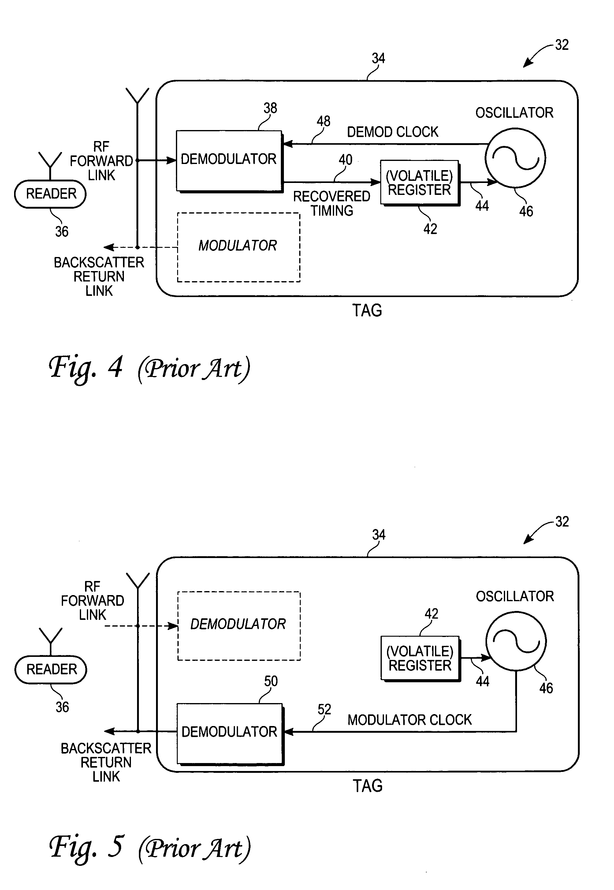
[0009] Accordingly, in the prior art system shown in FIGS. 4 and 5, the recovered timing signal 40 is stored within a volatile register that is utilized to calibrate the oscillator. However, a clock recovery operation is required by the demodulator 38 upon each power-up event, which may negatively impact the performance of the RFID tag 32.

Problems solved by technology

Furthermore, backscatter communications may be subject to regulatory restrictions, and may need to be compliant with one or more RFID communications specifications or standards.
A disadvantage of such arrangements is that they tend to be bulky, and high-power consumers.
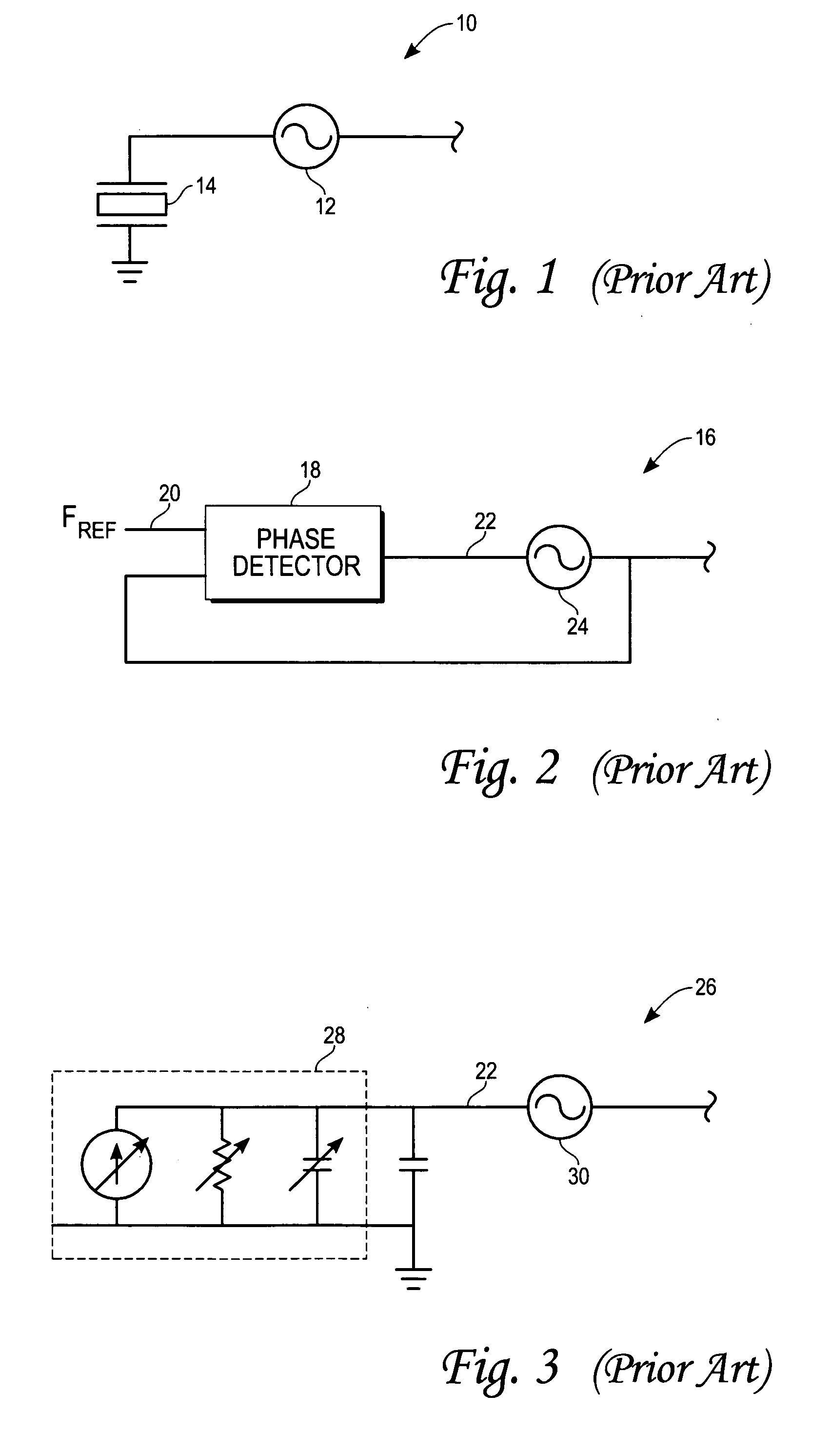
The disadvantages of the phase-locked loop arrangement 16 shown in FIG. 2 include the required provision of a reference frequency, a long start-up time, the provision of extra power for the phase detector 18, as well as the extra chip area requirements for provision of the phase detector 18.
Among the disadvantages of this arrangement are that the trimming arrangement may be expensive to build, and the configuration of the trimming arrangement 28 is permanent (i.e., the oscillator 30 cannot be dynamically calibrated).
However, a clock recovery operation is required by the demodulator 38 upon each power-up event, which may negatively impact the performance of the RFID tag 32.

Method used


Image

  • Method and system to calibrate an oscillator within an RFID circuit utilizing a test signal supplied to the RFID circuit
  • Method and system to calibrate an oscillator within an RFID circuit utilizing a test signal supplied to the RFID circuit
  • Method and system to calibrate an oscillator within an RFID circuit utilizing a test signal supplied to the RFID circuit

Examples

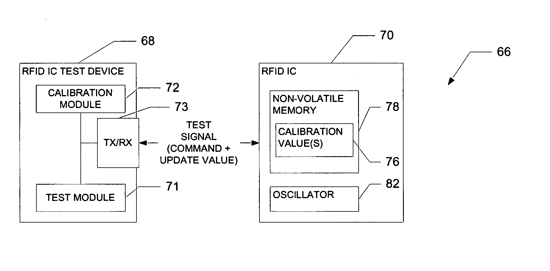

Embodiment Construction

[0030] A calibrated oscillator for an RFID system, and methods of manufacturing and operating the same, are described. In the following description, for purposes of explanation, numerous specific details are set forth in order to provide a thorough understanding of the present invention. It will be evident, however, to one skilled in the art that the present invention may be practiced without these specific details.

[0031]FIG. 6 is a block diagram illustrating multiple operation types 60 that may be performed by a radio-frequency identification (RFID) integrated circuit (IC) suitable for use within an RFID tag assembly. In an exemplary embodiment, an RFID tag may be a combination of an RFID circuit (e.g., an Integrated Circuit (IC)), and a coupled antenna (or antennae) to facilitate the reception and transmission of radio-frequency signals, the RFID circuit and the antenna(e) being located on a base material or substrate (e.g., a plastic or paper material) to thereby constitute an R...


PUM


Abstract

In accordance with one aspect of the present invention, there is provided a method of calibrating an oscillator within a radio-frequency identification (RFID) circuit for use in an RFID tag. The oscillator has an oscillation frequency. A calibration value is stored within a non-volatile memory associated with the RFID circuit. The oscillator is calibrated in accordance with the calibration value. The storing of the calibration value includes recovering a reference frequency from a test signal supplied to the RFID circuit, calculating the calibration value to correspond to a difference between the recovered reference frequency and the oscillator frequency, and writing the calibration value to the non-volatile memory.

Description

FIELD OF THE INVENTION [0001] An embodiment relates generally to the field of oscillator calibration and, more specifically, to an apparatus and a method to calibrate an oscillator for a radio-frequency identification (RFID) system. BACKGROUND OF THE INVENTION [0002] Radio-frequency identification tags (or transponders) require a reference frequency for a number of purposes. An RFID reader transmits RF power to RFID tags. RFID tags modulate reflected RF power to transmit data back to an RFID reader. The reflected RF is called ‘backscatter,’ and the link from the tag back to the reader is typically referred to as the ‘backscatter link. The backscatter modulation of course requires a backscatter frequency to which the relevant RFID reader is sensitive. Furthermore, backscatter communications may be subject to regulatory restrictions, and may need to be compliant with one or more RFID communications specifications or standards. An RFID tag also requires a demodulation frequency so as t...

Claims


Application Information

Patent Timeline
Patent Type & Authority Applications(United States)
IPC IPC(8): G01R35/00G06F19/00
CPCG01R35/005
Inventor DIORIO, CHRISTOPHER J.GUTNIK, VADIMHUMES, TODD E.
Owner IMPINJ
Why Eureka
Try Eureka