

Auger for snow throwing machine
a technology for snow throwing machines and augers, which is applied in the field of snow throwing machines, can solve the problems of limited damage to the individual flytes and not to the auger transmission or engin
- Summary
- Abstract
- Description
- Claims
- Application Information
AI Technical Summary
Benefits of technology
Problems solved by technology
Method used
Image

Examples
Embodiment Construction
[0020] The invention will now be described in the following detailed description with reference to the drawings, wherein preferred embodiments are described in detail to enable practice of the invention. Although the invention is described with reference to these specific preferred embodiments, it will be understood that the invention is not limited to these preferred embodiments. But to the contrary, the invention includes numerous alternatives, modifications and equivalents as will become apparent from consideration of the following detailed description.
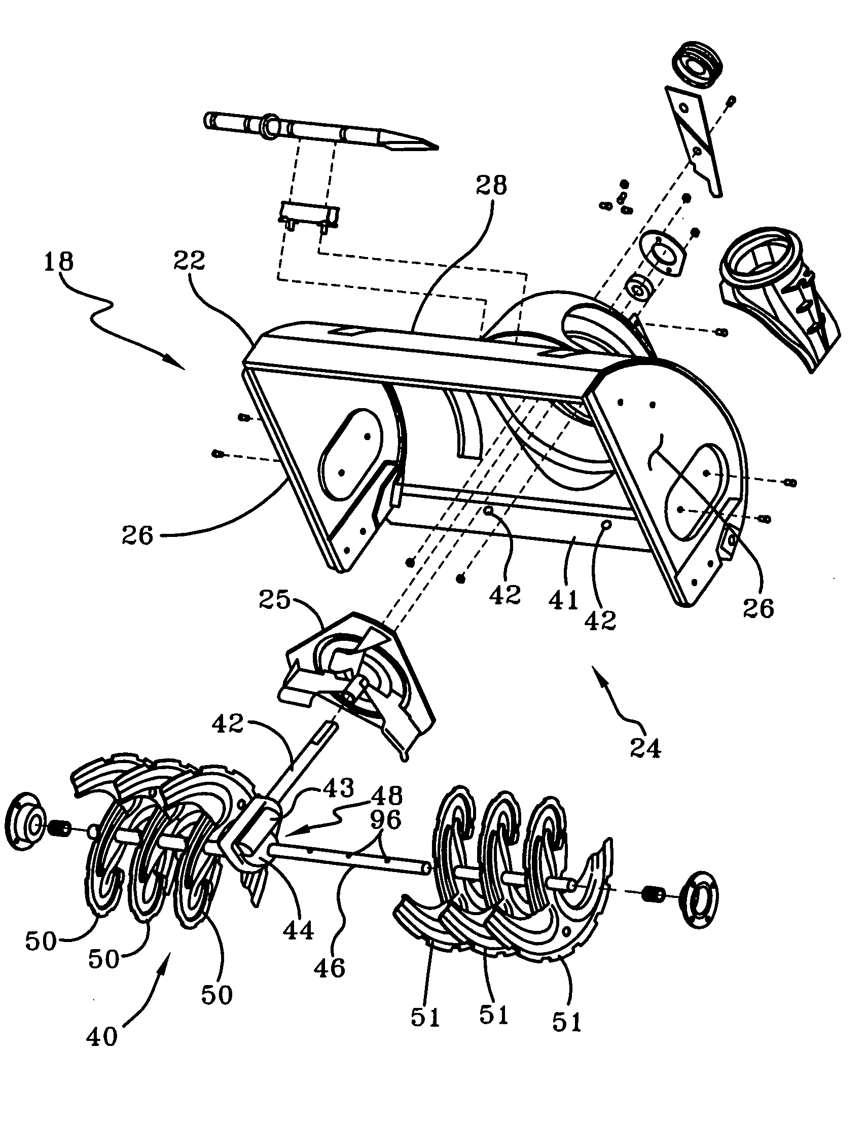
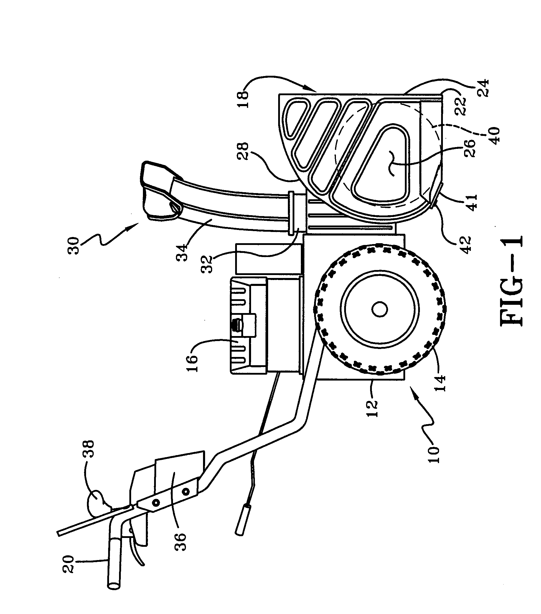
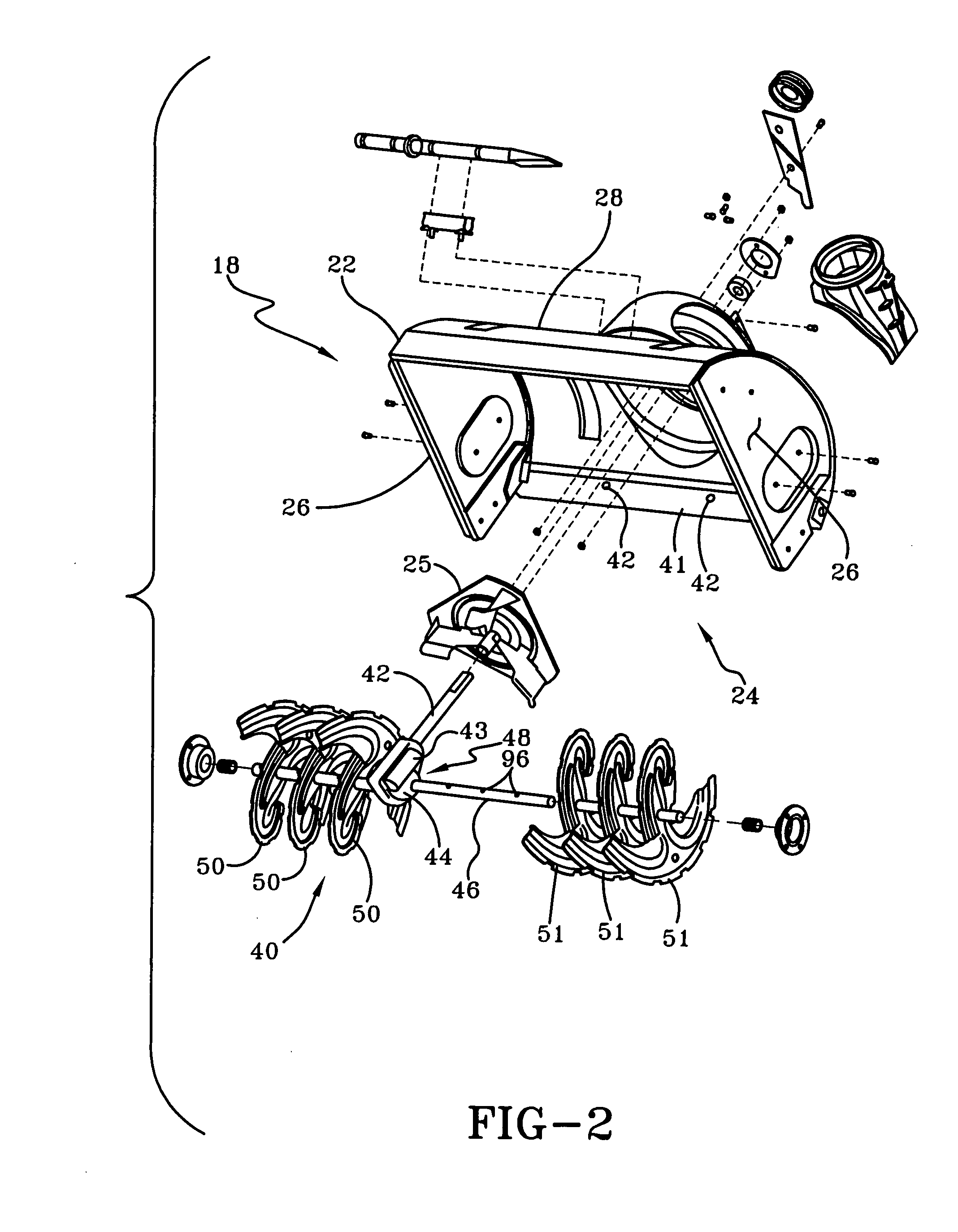
[0021] Referring now to FIG. 1, a walk-behind snow throwing machine is shown generally at 10. The snow thrower 10 includes a frame 12 and ground-engaging wheels 14, operatively coupled to the frame. A power source 16, such as an internal combustion engine or other suitable power source, is fixedly attached to the frame 12 and provides power for operating a snow-gathering unit, indicated generally 18, attached to the front end of t...
PUM
 Abstract
Description
Claims
Application Information