Method and apparatus for head positioning control with disturbance compensation in a disk drive

Inactive Publication Date: 2005-11-03
KK TOSHIBA
View PDF12 Cites 8 Cited by
  • Summary
  • Abstract
  • Description
  • Claims
  • Application Information

AI Technical Summary

Benefits of technology

[0009] In accordance with an aspect of the present invention, there is provided a disk drive including a facility of a

Problems solved by technology

Accordingly, when the head positioning control system of the prior art is applied to the disk drive, there are problems

Method used


Image

  • Method and apparatus for head positioning control with disturbance compensation in a disk drive
  • Method and apparatus for head positioning control with disturbance compensation in a disk drive
  • Method and apparatus for head positioning control with disturbance compensation in a disk drive

Examples


Example

First Embodiment

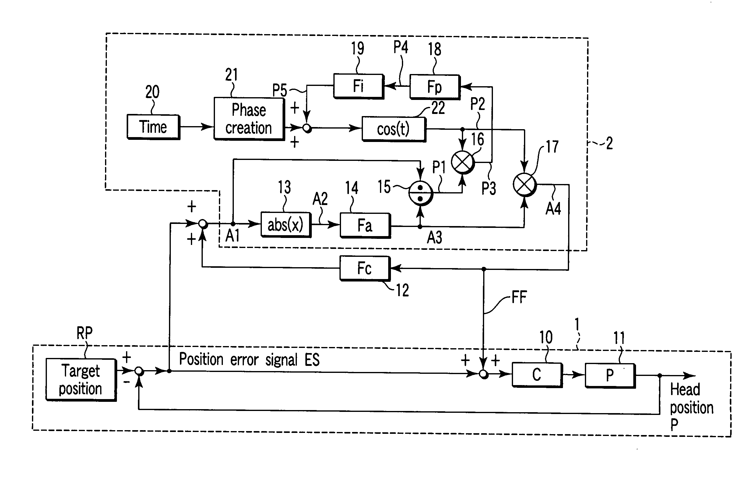
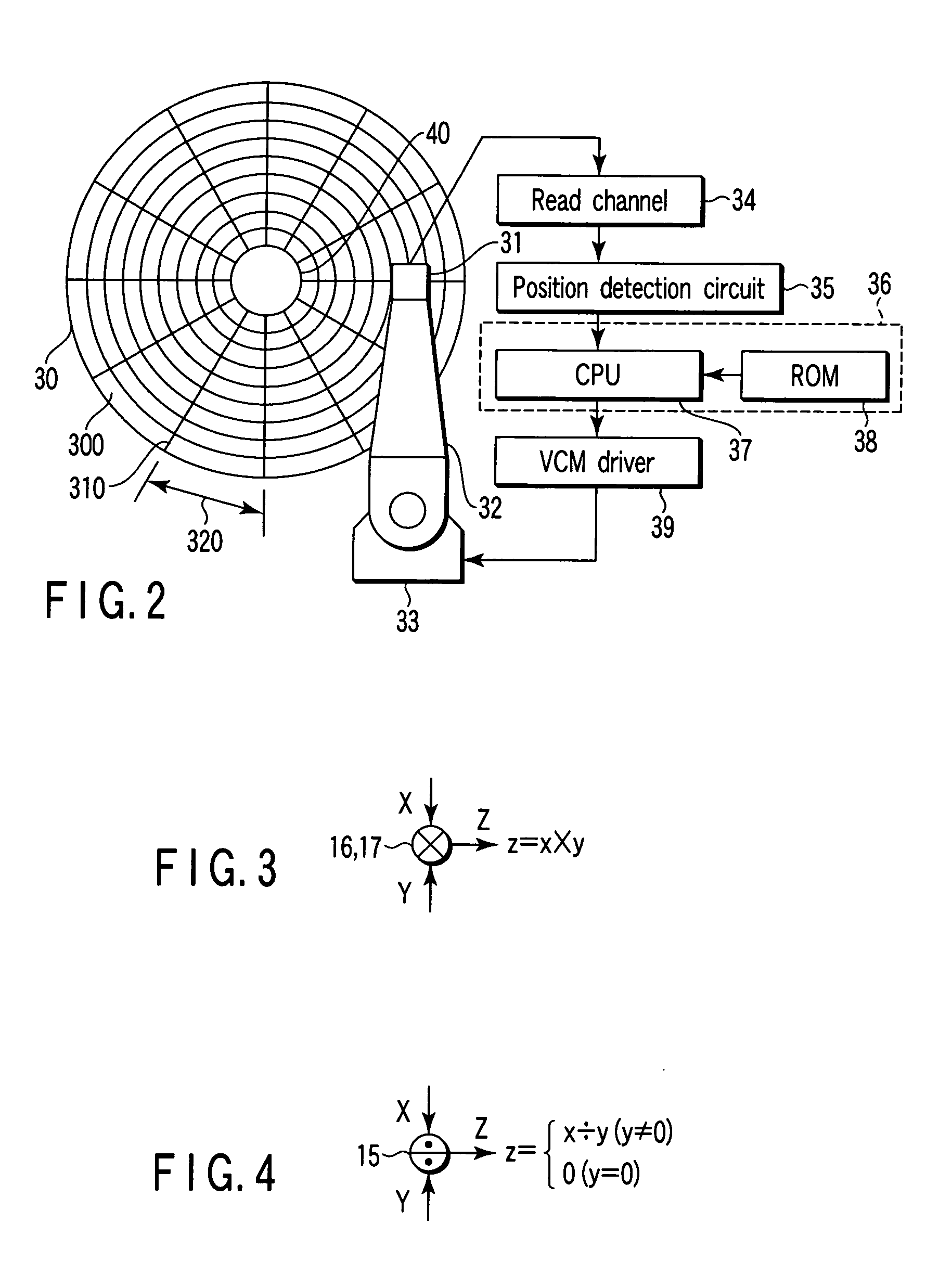
[0027]FIG. 1 is a block diagram showing a configuration of a head positioning control system according to a first embodiment of the invention. FIG. 2 is a block diagram showing a main part of a disk drive according to the first embodiment.

(Configuration of Disk Drive)

[0028] As shown in FIG. 2, the disk drive of the first embodiment is a hard disk drive. The disk drive includes a disk medium 30, a head 31, and a head positioning control system (servo system).

[0029] The disk medium 30 is rotated by a spindle motor 40. Many concentric tracks 300 which are of a data recording area are formed on the disk medium 30. Servo sectors are arranged in each track 300. Each servo sector includes a servo area 310 in which servo data (position information) is recorded and a data sector 320 serving as an area in which user data is recorded.

[0030] The head 31 is mounted on an actuator 32 which is rotated by a voice coil motor (VCM) 33. The actuator 32 positions the head 31 at a ...

Example

Second Embodiment

[0060]FIG. 14 is a view showing a configuration of a head positioning control system according to a second embodiment of the invention.

[0061] The head positioning control system of the second embodiment includes a spectrum detection unit 25 which detects a spectrum of the position error signal ES and a selection unit 26 which changes the spectrum detection and the amplitude / phase detection.

[0062] Because the center frequency of the disturbance is changed by the vibration state applied to the disk drive and the like, it is difficult to previously estimate a certain value. Therefore, the frequency showing the maximum amplitude is detected from the frequency spectrum of the position error, and the frequency showing the maximum amplitude is set as the center frequency of the phase detection unit in the FF control system 2. As a result, even if the vibration state of the disturbance is changed, the phase of the disturbance is precisely detected, which allows the posit...


PUM


Abstract

A head positioning control system which is applied to a disk drive is disclosed. The system includes a feedback control system which performs head positioning control of a head and a feedforward control system. The feedforward control system detects the amplitude and phase of a disturbance based on the position error between the position of the head and a target position. The feedforward control system computes a disturbance compensation value for eliminating the disturbance to output the disturbance compensation value to the feedback control system based on each detection result of the amplitude and the phase.

Description

CROSS-REFERENCE TO RELATED APPLICATIONS [0001] This application is based upon and claims the benefit of priority from prior Japanese Patent Application No. 2004-134500, filed Apr. 28, 2004, the entire contents of which are incorporated herein by reference. BACKGROUND OF THE INVENTION [0002] 1. Field of the Invention [0003] The present invention relates to a disk drive, and particularly to head positioning control technology with disturbance compensation. [0004] 2. Description of the Related Art [0005] Generally a head positioning control system for positioning a head at a target position (target track) on a disk medium is incorporated into a disk drive typically including a hard disk drive. [0006] In the case of a disturbance having a large influence, such as a vibration and an impact, head positioning accuracy is decreased in the head positioning control system. Therefore, a disturbance compensation function of suppressing the disturbance which affects the head positioning accuracy...

Claims


Application Information

Patent Timeline
IPC IPC(8): G11B5/596G11B21/10
CPCG11B5/59627
Inventor IWASHIRO, MASAFUMI
Owner KK TOSHIBA
Why Eureka
Try Eureka