Method of detecting and locating a source of partial discharge in an electrical apparatus

a technology of partial discharge and electrical equipment, which is applied in direction finders using ultrasonic/sonic/infrasonic waves, instruments, etc., can solve the problems of wasting time, affecting the accuracy of measurement, so as to save time and improve accuracy. , the effect of less expensiv

Inactive Publication Date: 2005-11-03
ALSTOM TECH LTD
View PDF16 Cites 25 Cited by
  • Summary
  • Abstract
  • Description
  • Claims
  • Application Information

AI Technical Summary

Benefits of technology

[0018] A particular object is to enable the partial discharge to be located with great accuracy. Accurate knowledge of the site of origin of partial discharges saves time and is therefore less expensive, since it then enables the malfunction of apparatus to be diagnosed more quickly and this makes it easier to determine what action needs to be taken to put the apparatus back into working order.
[0019] Another object of the invention is to enable localization to be performed simply in a manner that can be adapted to any type of electrical apparatus. In addition, another object of the invention is to enable localization to be performed quickly.

Problems solved by technology

The defect may be due to a breakdown in the transformer insulation.
Measurement accuracy is mediocre.
However the measurement device rapidly becomes very bulky.
However a measurement cycle then takes time and the accuracy of localization remains mediocre since the detected signals do not necessarily come from the same source of partial discharge.
Although the approximation described in the above paragraph simplifies calculations, it reduces the accuracy of the localization.
However that is not possible with the arrangement described in patent [3].
The arrangement of three detectors suggested in patent [3] is therefore not sufficient.
It is therefore necessary to use a plurality of arrangements of three detectors, which makes that method very complicated to use.

Method used


Image

  • Method of detecting and locating a source of partial discharge in an electrical apparatus
  • Method of detecting and locating a source of partial discharge in an electrical apparatus
  • Method of detecting and locating a source of partial discharge in an electrical apparatus

Examples


Embodiment Construction

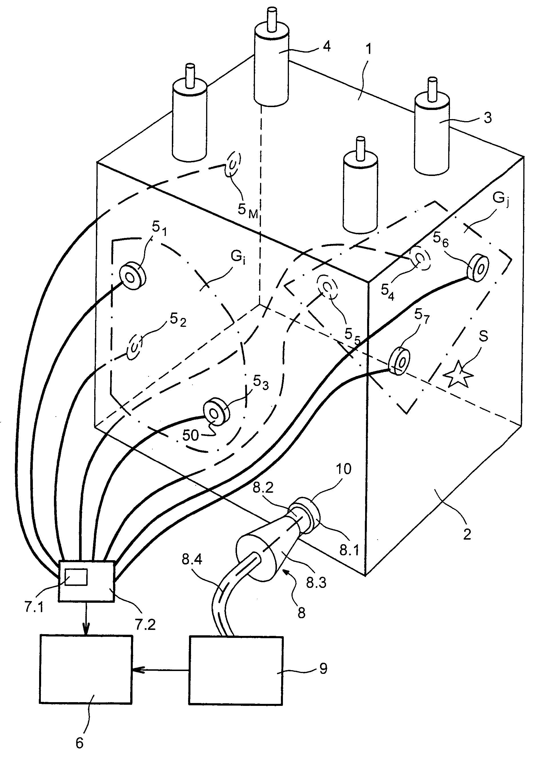
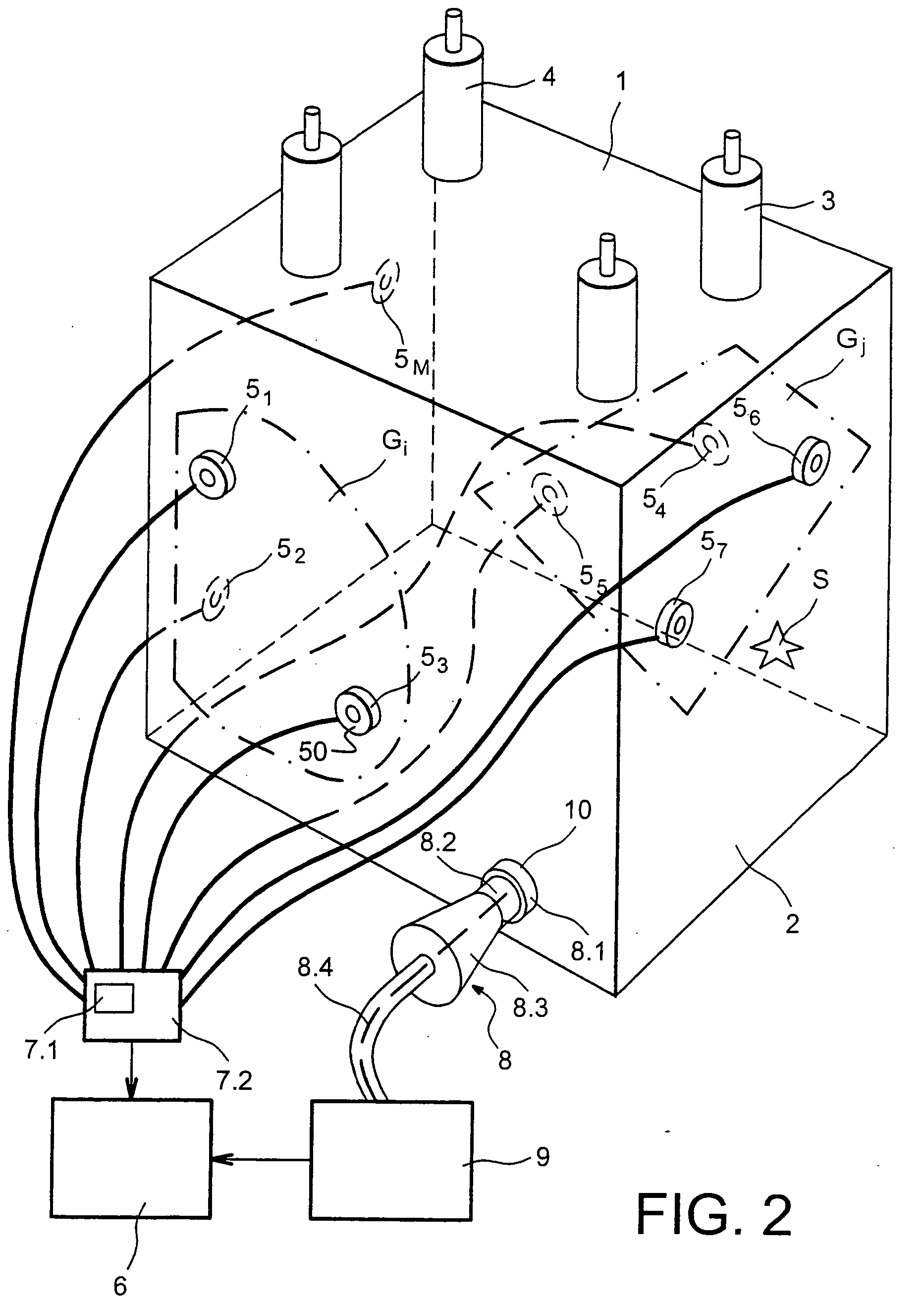
[0060] Reference is made to FIG. 2 which shows an example of apparatus used for implementing the method of the invention for detecting and localizing a source of partial discharge in an electrical apparatus. It is assumed that the electrical apparatus is a high voltage transformer and that it is live. The transformer comprises windings and cores which are not shown so as to avoid cluttering the figure, and which are located inside an enclosure 1. The enclosure 1 is made of an acoustically-conductive material such as steel sheet.

[0061] In addition to the electrical apparatus, the enclosure 1 contains an acoustically-conductive medium 2. The acoustically-conductive medium 2 may be oil or some other fluid. The medium 2 serves to insulate the conductors of the windings electrically from one another. It may also serve to cool said windings.

[0062] The enclosure 1 is fitted with high voltage feedthroughs 3 and low voltage feedthroughs 4. The apparatus for detecting and localizing a sourc...


PUM


Abstract

A method of detecting and localizing a source of partial discharge in an electrical apparatus placed in an enclosure containing an acoustically-conductive fluid. The method consists in:
    • positioning (31) acoustic detectors and acquiring the positions of the detectors;
    • defining (35) groups of detectors, each group including at least three detectors;
    • ensuring (37) that each group is free from any triangle having vertices embodied by three detectors in which at least one angle lies outside a range of angles, and otherwise eliminating the group;
    • for each non-eliminated group, calculating (38) an approximate position for the source;
    • ensuring (39) that each non-eliminated group is free from any triangle having vertices embodied by two detectors of the group and by the approximate position, including at least one angle that lies outside the range, and otherwise eliminating the group; and
    • calculating (43) the looked-for position of the source by averaging the approximate positions of all or some of the non-eliminated groups.

Description

TECHNICAL FIELD [0001] The present invention relates to a method of detecting and locating a source of partial discharge in an electrical apparatus such as a transformer. This method, for use during maintenance tests, for example, serves to detect and locate any source of partial discharge in the electrical apparatus simply, quickly, and accurately. The manufacturers of such electrical apparatuses and their users regularly check for the appearance of partial discharges, since they are the cause of apparatus malfunctions and can lead to destruction of the apparatus. STATE OF THE PRIOR ART [0002] Partial discharges relate to electrical charge being emitted inside the electrical apparatus due to a fault in its electrical insulation. The electrical apparatus lies within an enclosure containing a fluid that conducts sound. For a high voltage transformer, its windings are generally insulated with paper that has been impregnated in a dielectric fluid such as oil. Other transformers are of ...

Claims


Application Information

Patent Timeline
Patent Type & Authority Applications(United States)
IPC IPC(8): G01R31/12
CPCY10S367/907G01R31/1209
Inventor KUPPUSWAMY, RAJALOUISE, SEBASTIENNZIHOU, NIEMET
Owner ALSTOM TECH LTD
Why Eureka
Try Eureka