
Outboard motor engine speed control system

a technology of speed control system and outboard motor, which is applied in the direction of motor-driven power plants, marine propulsion, vessel construction, etc., can solve the problems of reducing the straight-forward (course-holding) ability of boats, tedious and complex operation, and reducing the straight-forward ability of boats, so as to enhance the operation and simplify the operation

Inactive Publication Date: 2005-11-03
HONDA MOTOR CO LTD
View PDF2 Cites 26 Cited by
  • Summary
  • Abstract
  • Description
  • Claims
  • Application Information

AI Technical Summary

Benefits of technology

The present invention aims to improve the speed control of outboard motors on boats by providing a system that simplifies the process and enhances the overall feel of operation.

Problems solved by technology

The technical problem addressed in this patent text is the inconvenience and complexity of synchronizing the engine speeds of outboard motors in order to improve the boat's straight-forwarding ability and to utilize outboard motor speed differentiation positively for improving boat turning performance.

Method used


Image

  • Outboard motor engine speed control system
  • Outboard motor engine speed control system
  • Outboard motor engine speed control system

Examples


Embodiment Construction

[0018] Here follows a description of preferred embodiment of an outboard motor engine speed control system according to the invention made with reference to the appended drawings.

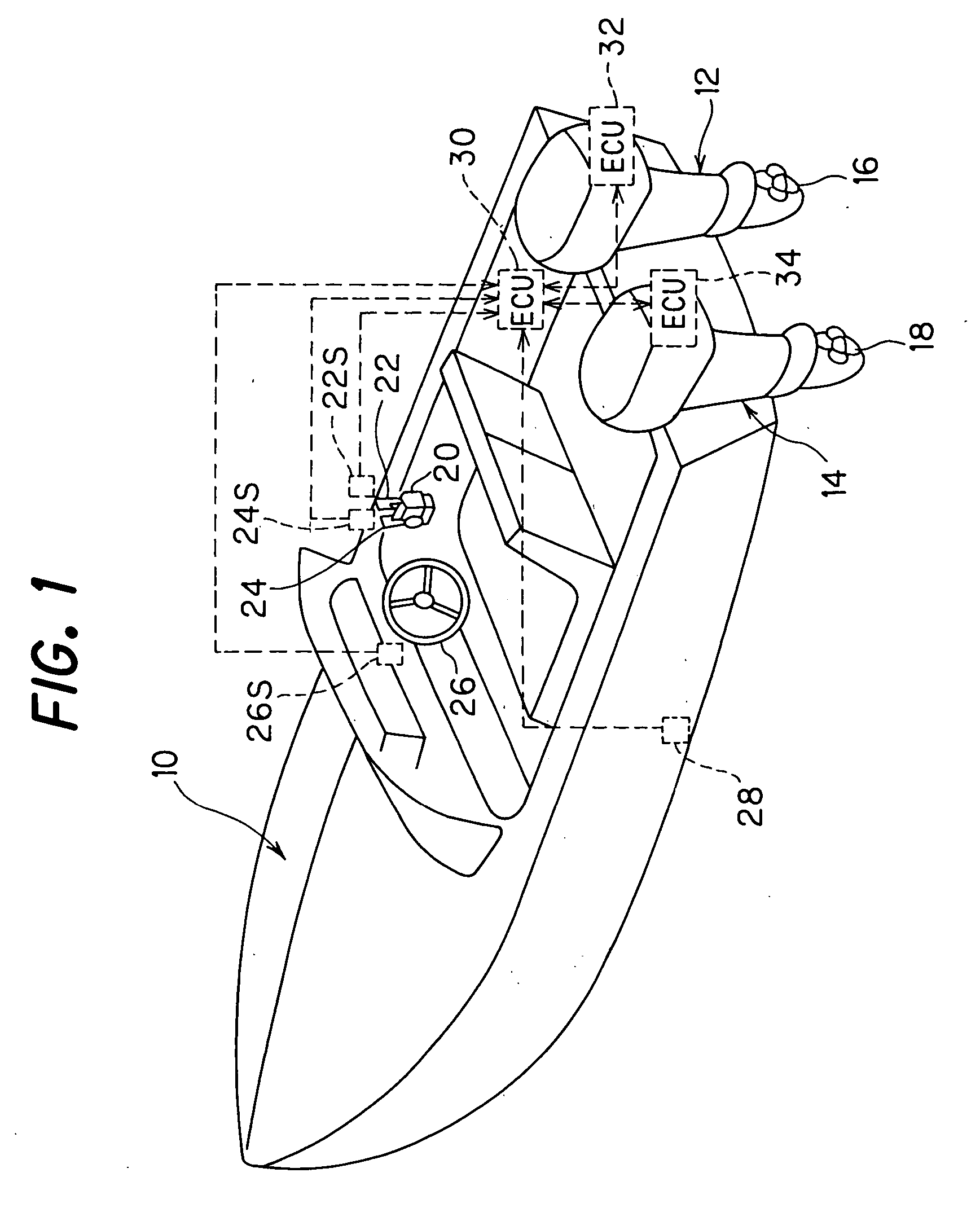
[0019]FIG. 1 is an overall schematic view of an outboard motor engine speed control system according to the embodiment of the invention, with primary focus on the outboard motor.

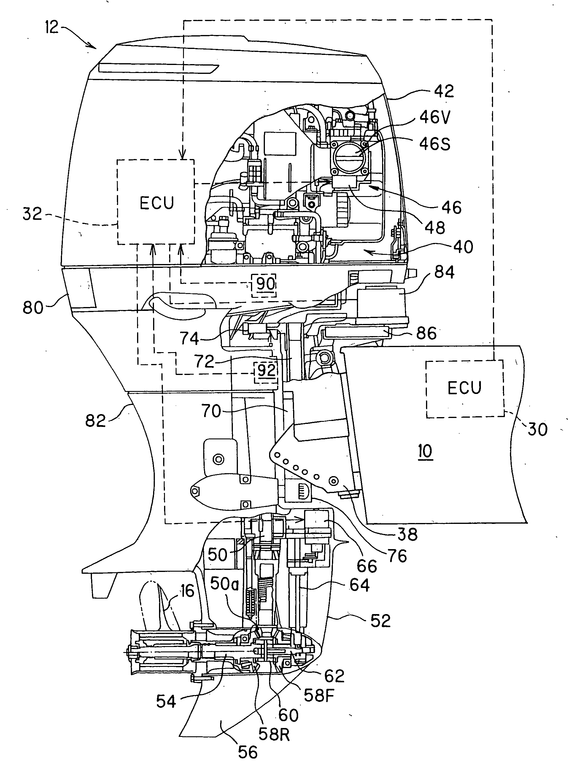
[0020] As shown in FIG. 1, a plurality of, more specifically two outboard motors are mounted at the stem of a hull (boat) 10. The boat 10 thus has what is called a dual motor configuration. In the following, the outboard motor designated by the symbol 12 in the drawings (the outboard motor on the right (starboard) side relative to the direction forward travel) will be called the “first outboard motor” and that designated by the symbol 14 (the one on the left (port) side) will be called the “second outboard motor.”

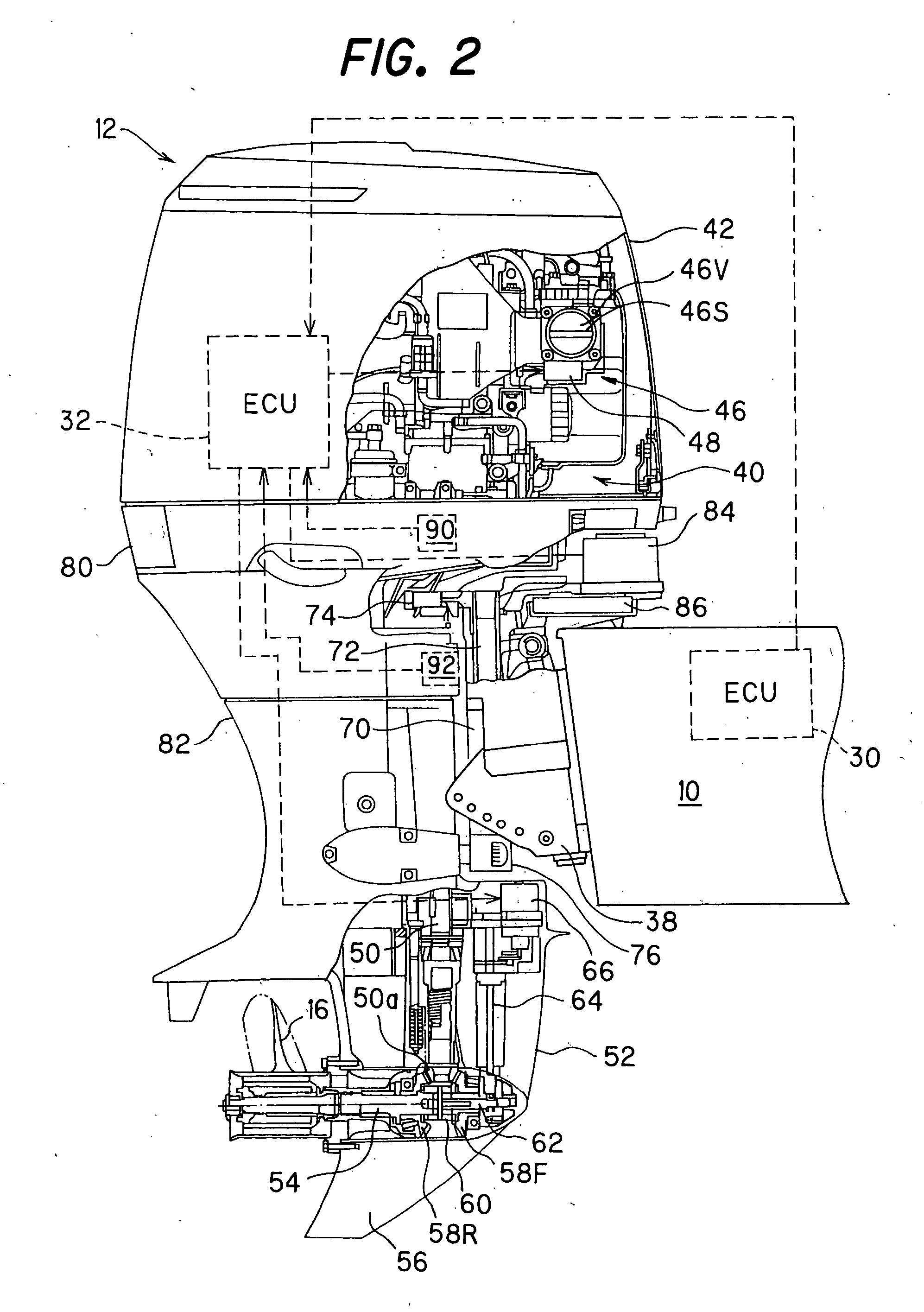
[0021] The first and second outboard motors 12, 14 are equipped with internal combustion engines (not shown in FIG. 1) ...


PUM


Abstract

An outboard motor engine speed control system includes two outboard motors, sensors which detect a travel speed of the boat and the engine speeds of the outboard motors, and a controller which controls the engine speeds of the outboard motors to be synchronized with a highest one of the detected engine speeds when the boat travel speed is equal to or higher than a predetermined value, while controlling the engine speeds of the outboard motors to be synchronized with a lowest one of the detected engine speeds when the boat travel speed is lower the predetermined value. The operations involved in engine speed control of the outboard motors mounted on the boat are thereby simplified and the feel of operation is enhanced.

Description


Claims


Application Information

Patent Timeline
Owner HONDA MOTOR CO LTD
Learn More