Shielded intraocular probe for improved illumination or therapeutic application of light

a technology of intraocular probes and shielded lenses, applied in the field of surgical instruments, can solve the problems of glare, difficult to distinguish using conventional illumination, and structure that is nearly transparen

Active Publication Date: 2005-11-03
CONNOR CHRISTOPHER S
View PDF4 Cites 72 Cited by
  • Summary
  • Abstract
  • Description
  • Claims
  • Application Information

AI Technical Summary

Benefits of technology

[0019]FIG. 5a shows a microscope view of an anterior capsule illuminated by a shielded beam according to one embodiment of the present invention, giving forward and downward illumination without glare.

Problems solved by technology

These structures, which are nearly-transparent, are difficult to distinguish using conventional illumination due to the small amount of light scatter which they produce when diffusely lit.
One drawback of conventional intraocular illuminators is that light

Method used


Image

  • Shielded intraocular probe for improved illumination or therapeutic application of light
  • Shielded intraocular probe for improved illumination or therapeutic application of light
  • Shielded intraocular probe for improved illumination or therapeutic application of light

Examples


Embodiment Construction

[0022] Reference will now be made in detail to the preferred embodiments of the present invention, examples of which are illustrated in the accompanying drawings.

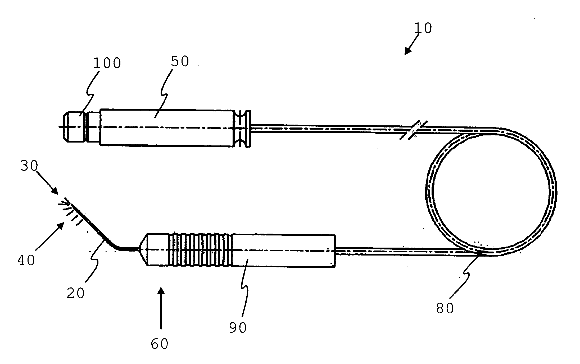
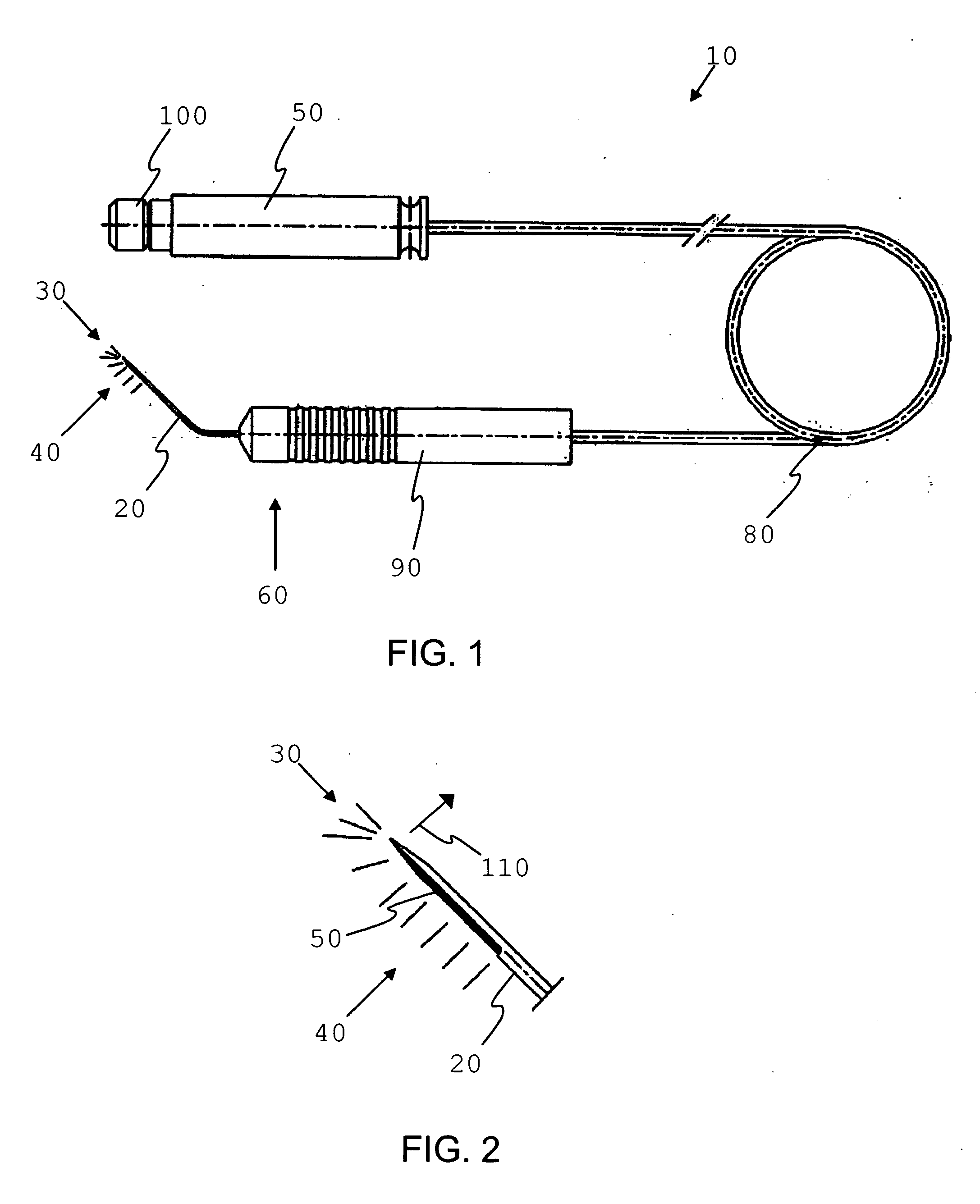
[0023] As shown in FIGS. 1 and 2, an intraocular light probe 10 has a mask or shield 20 affixed at its distal end 60 thereof which forms a directed light beam 30, 40 for intraocular illumination of, or application of therapeutic light to, target tissues. The mask or shield 20 is preferably opaque or semi-opaque, and may be constructed of metal, polymer, Teflon, or other suitable surgical-grade material. The mask or shield 20 may be constructed of a soft, semi-rigid or rigid material, but may be made rigid enough to serve as the shaft of an instrument with a probe or manipulator at its distal tip. The shape of the mask or shield can be flat, curved or circular, with an opening or aperture 50 along one side.

[0024] The opening or aperture 50 extends along at least a portion of the length of the mask or shield 20. The apertur...


PUM


Abstract

An intraocular light probe has a mask or shield affixed at its distal end thereof which forms a directed light beam for intraocular illumination of target tissues or intraocular application of therapeutic light. The mask or shield serves to more fully focus, intensify and direct the beam toward the target tissues. The mask or shield also helps direct light away from other tissues and away from the eyes of the surgeon. This lessens unwanted glare. By placing a light probe beneath a surgical instrument such as a phacoemulsifier or vitrector, laser, cutting instrument (e.g., scissors or knife), forceps or probe/manipulator, whether as part of or separate from an infusion sleeve, a mask or shield effect is created. This has the same benefits of directing the beam toward target tissues, away from other tissues and away from the eyes of the surgeon. The mask or shield is opaque or semi-opaque and made of a soft, semi-rigid or rigid material. The shield can be rigid enough to serve as the shaft of an instrument with a probe or manipulator at its distal tip. It may also be reflective on the side adjacent to the fiber bundle to help direct, magnify, and intensify the beam of light. The shape of the shield can be flat, curved or circular with an opening along one side. The mask/shield can be removed from the fiberoptic light for sterilization. The device of the invention is preferably introduced into the eye via the primary or side-port incision to provide intraocular cross-lighting of tissues during surgical procedures such as cataract surgery, corneal surgery, vitrectomy, intraocular lens implantation, refractive surgery, glaucoma surgery and vitreo/retinal surgery.

Description

[0001] This application claims priority to U.S. Provisional Patent Application No. 60 / 566,619 filed Apr. 30, 2004, the entire disclosure of which is incorporated herein by reference.[0002] This application includes material which is subject to copyright protection. The copyright owner has no objection to the facsimile reproduction by anyone of the patent disclosure, as it appears in the Patent and Trademark Office files or records, but otherwise reserves all copyright rights whatsoever. FIELD OF THE INVENTION [0003] The present invention relates in general to the field of surgical instruments, and in particular to a shielded intraocular probe for insertion into the eye that provides improved illumination of ocular structures. BACKGROUND OF THE INVENTION [0004] Extraocular and intraocular slit beam illuminators are known and used in office and surgical settings for illuminating ocular structures, such as the cornea and lens surfaces and intraocular fluids and tissues including retina...

Claims


Application Information

Patent Timeline
IPC IPC(8): A61B1/07A61B18/20A61B19/00A61F9/007A61F9/008A61N5/06
CPCA61B2019/5206A61F9/00736A61F9/0084A61N5/0601A61B19/5202A61F9/008A61B90/30A61B2090/306
Inventor CONNOR, CHRISTOPHER S.
Owner CONNOR CHRISTOPHER S
Why Eureka
Try Eureka