Tibial prosthesis convertible in vivo to a modular prosthesis

a modular, tibial technology, applied in the field of surgical implantable joint prosthesis, can solve the problems of possible bone loss or fracture, difficult revision surgery, and difficult to avoid micromotion with modular components

Inactive Publication Date: 2005-11-03
BIOMET MFG CORP
View PDF41 Cites 60 Cited by
  • Summary
  • Abstract
  • Description
  • Claims
  • Application Information

AI Technical Summary

Benefits of technology

[0013] Another object of the present invention is to provide advantages of a nonmodular joint prosthesis, including the virtual absence of micromotion, and yet allow a surgeon performing revision surgery to change to a modular bearing without disturbing the base member and thereby jeopardizing fixation.

Problems solved by technology

Micromotion is very difficult to avoid with modular components due to the need for clearances between bearing and base to ensure that they fit together during assembly in the operating room.
Unfortunately, a nonmodular prosthesis has heretofore made revision surgery more difficult in that the entire prosthetic component must be removed and replaced.
In addition to the extra operating time involved and extraction tools required, such as described in U.S. Pat. No. 4,459,985 to McKay, removal and replacement of the base requires sacrificing the existing fixation to the bone and has associated complications, including possible bone loss or fracture and the difficulty of reestablishing solid fixation.

Method used


Image

  • Tibial prosthesis convertible in vivo to a modular prosthesis
  • Tibial prosthesis convertible in vivo to a modular prosthesis
  • Tibial prosthesis convertible in vivo to a modular prosthesis

Examples


Embodiment Construction

[0030] For the purpose of promoting an understanding of the principles of the invention, reference will now be made to the embodiment illustrated in the drawings and specific language will be used to describe the same. It will nevertheless be understood that no limitation of the scope of the invention is thereby intended, such alterations and further modifications in the illustrated device, and such further applications of the principles of the invention as illustrated therein being contemplated as would normally occur to one skilled in the art to which the invention relates.

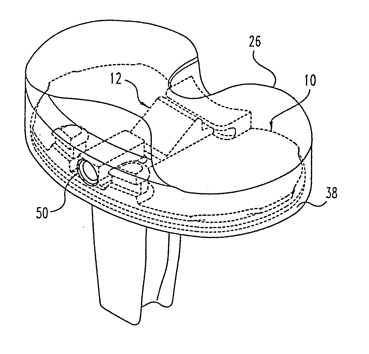
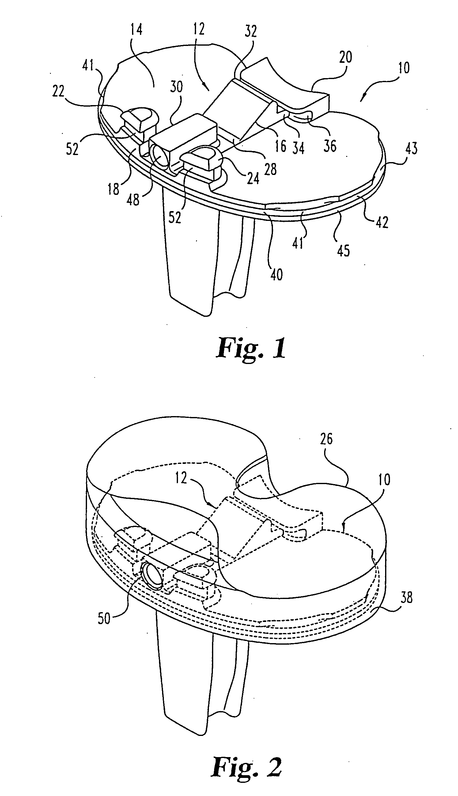
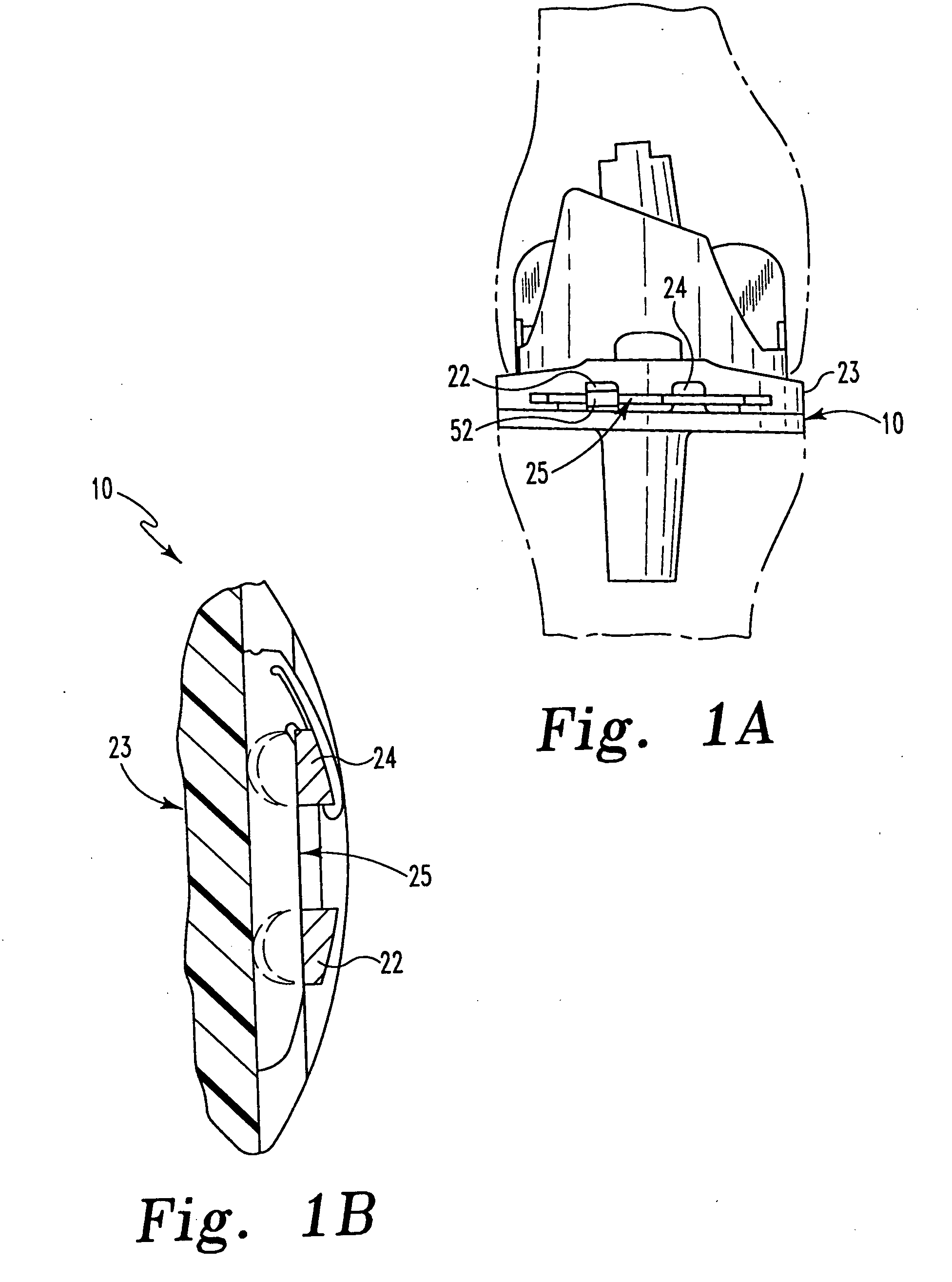
[0031] With reference to FIG. 1, the preferred embodiment of the present invention includes a tibial base or tray 10 and a release member 12 slidably mounted on the intercondylar portion thereof on a smooth, flat superior surface 14. Release member 12 includes a wedge portion 16 and extends between the anterior edge 18 of base 10 and a retaining rail 20 extending superiorly from the posterior edge of the base. ...


PUM


Abstract

A nonmodular tibial prosthesis having a retainer for a modular bearing on the superior surface of a tibial base, a nonmodular primary bearing directly molded to the base, and a mechanical release member mounted on the tibial base in contact with the nonmodular primary bearing. The release member includes a wedge portion with a superiorly posteriorly inclined face, and is designed to be driven anteriorly upon actuation so as to force the primary bearing off of the tibial base, after which the primary bearing and release member are removed and replaced with a modular bearing.

Description

CROSS-REFERENCE TO RELATED APPLICATIONS [0001] This application is a continuation of application Ser. No. 10 / 328,453, filed Dec. 23, 2002, now U.S. Pat. No. 6,916,340, issued Jul. 12, 2005, which is a continuation of application Ser. No. 09 / 303,945, filed May 3, 1999, now U.S. Pat. No. 6,500,208, issued Dec. 31, 2002, which is a continuation of application Ser. No. 09 / 173,940, filed Oct. 16, 1998, abandoned.BACKGROUND OF THE INVENTION [0002] This invention relates to surgically implantable joint prostheses and, more particularly, to a joint prosthesis that combines advantages of modular and nonmodular prostheses. [0003] Artificial joints of the human body, including in particular knee and hip joints, have been available for 50 years or more and have been the subject of intense development for at least the last 20 years. The earliest designs provided metal-to-bone or metal-to-metal contact between the articulating surfaces of a joint. Friction and wear were significantly reduced in s...

Claims


Application Information

Patent Timeline
Patent Type & Authority Applications(United States)
IPC IPC(8): A61F2/00A61F2/30A61F2/34A61F2/38A61F2/46
CPCA61F2/30744Y10S623/908A61F2/389A61F2/4637A61F2002/30133A61F2002/30383A61F2002/30387A61F2002/30481A61F2002/30507A61F2002/30535A61F2002/30604A61F2002/30614A61F2002/30797A61F2002/30878A61F2002/4623A61F2002/4641A61F2220/0025A61F2230/0015A61F2250/0058A61F2310/00023A61F2310/00029A61F2/34A61F2/4603
Inventor METZGER, ROBERT G.ASNIS, STANLEY E.
Owner BIOMET MFG CORP
Why Eureka
Try Eureka